Software
Almost everything that happens in the rocket is controlled by software running on the rocket's three processors. This includes updating the LED displays, flashing the lights, turning the thrusters on and off in response to joystick commands, shaking the rocket with the paint-shaker, and animating the takeoff sequence. The code is all written in C, using AVR libc for the Atmega328, and our own simple operating system.As described in the electronics section, the rocket's LED panels were designed so that they could be connected together in a bus, with up to 8 panels being controlled by a single processor. The 8-panel maximum is an assumption baked right into the bus definition, since we reserved only 3 wires (on a parallel bus) as the board-select lines. As our ambitions for the rocket grew, we realized 8 panels wouldn't be enough, so we built a second bus with another 4 panels controlled by an independent second processor. The processors coordinate by exchanging messages using a simple TWI-based network protocol. Of course, once we had two, three wasn't a big leap: the audio board has its own (third) processor, and is also connected via the TWI network.
The majority of the application logic runs on one processor. The other two can be thought of as peripheral processors: the main processor exchanges messages with them to request display updates, initiate audio output, or retrieve inputs from keys and knobs. The peripheral processors don't do any real sequencing or coordination.
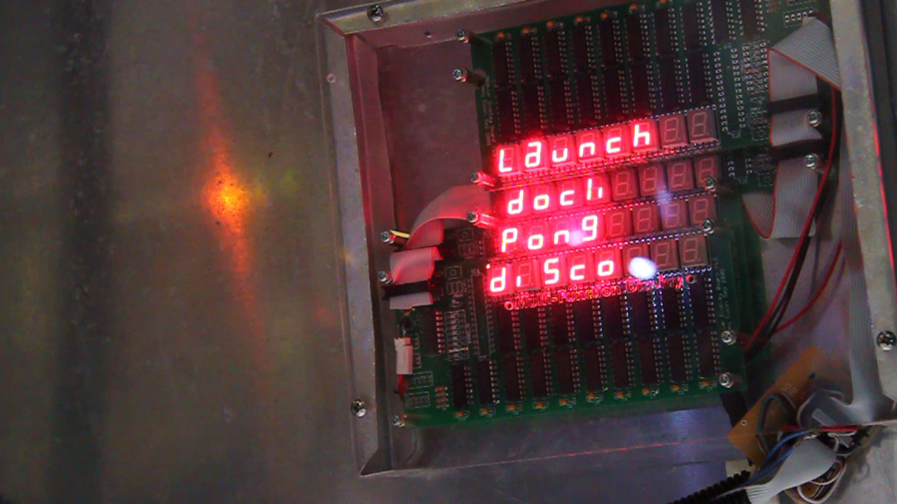 The main processor has several major modes, selectable via a menu
displayed on the four-line display:
The main processor has several major modes, selectable via a menu
displayed on the four-line display:
 Takeoff
In takeoff mode, the pilot is first asked to enter
a four-digit code to initiate the takeoff sequence. The
4-line display starts to display a big-number countdown and a
request to the audio board starts the audio track. The countdown sound effect,
incidentally, is the actual audio from the
Apollo 11 launch.
At zero, the thrusters fire, the paint-shaker is activated, and the lights
and LED displays are all commanded to flicker until the "boost stage" is complete.
Takeoff
In takeoff mode, the pilot is first asked to enter
a four-digit code to initiate the takeoff sequence. The
4-line display starts to display a big-number countdown and a
request to the audio board starts the audio track. The countdown sound effect,
incidentally, is the actual audio from the
Apollo 11 launch.
At zero, the thrusters fire, the paint-shaker is activated, and the lights
and LED displays are all commanded to flicker until the "boost stage" is complete.
Once the launch is complete, most of the other displays ("Lunar Distance", "Speed", "Azimuth/Elevation/Roll", and so on) start to display slowly changing numbers.
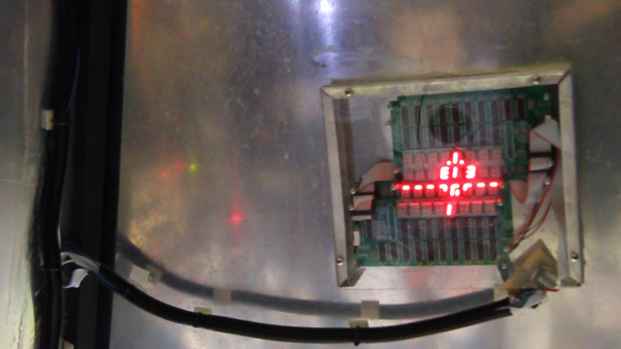 Docking
When the pilot is ready to return to Earth, Docking Mode
puts a crosshair on the 4-line display with a slowly growing
circle that represents the rocket's current alignment with its
docking clamp. The pilot's job is to keep the rocket aligned
using the joystick. Moving the joystick fires the (real) thrusters
and moves the (virtual) spaceship. The ship won't dock unless
the pilot is successful at keeping the ship aligned in the
crosshairs!
Docking
When the pilot is ready to return to Earth, Docking Mode
puts a crosshair on the 4-line display with a slowly growing
circle that represents the rocket's current alignment with its
docking clamp. The pilot's job is to keep the rocket aligned
using the joystick. Moving the joystick fires the (real) thrusters
and moves the (virtual) spaceship. The ship won't dock unless
the pilot is successful at keeping the ship aligned in the
crosshairs!
Disco! Lunar missions are serious business, but it's okay to get funky once in a while. Disco mode unleashes the pilot's inner groove by flashing all the rocket's LEDs in color order and strobing the overhead lights.
Other functions of the software include:
- Joystick thruster control
The pilot's joystick is a vintage PC
joystick whose X and Y motions control two potentiometers. Each of
these pots, with a voltage divider circuit, is monitored by two of the
processors analog-to-digital converters. One of the
panels displays X
and Y position on one of the panels, and if they exceed a
threshold, fire one of the thrusters. Pushing the "fire" button
turns on the "engine" (i.e., paint-shaker).
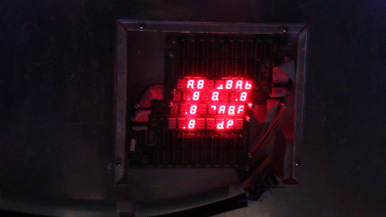
The panel shown at the right is a "bar graph" that shows thruster pressure. Each time a thruster is fired, one of the green bars goes high, then decays after the thruster is released.

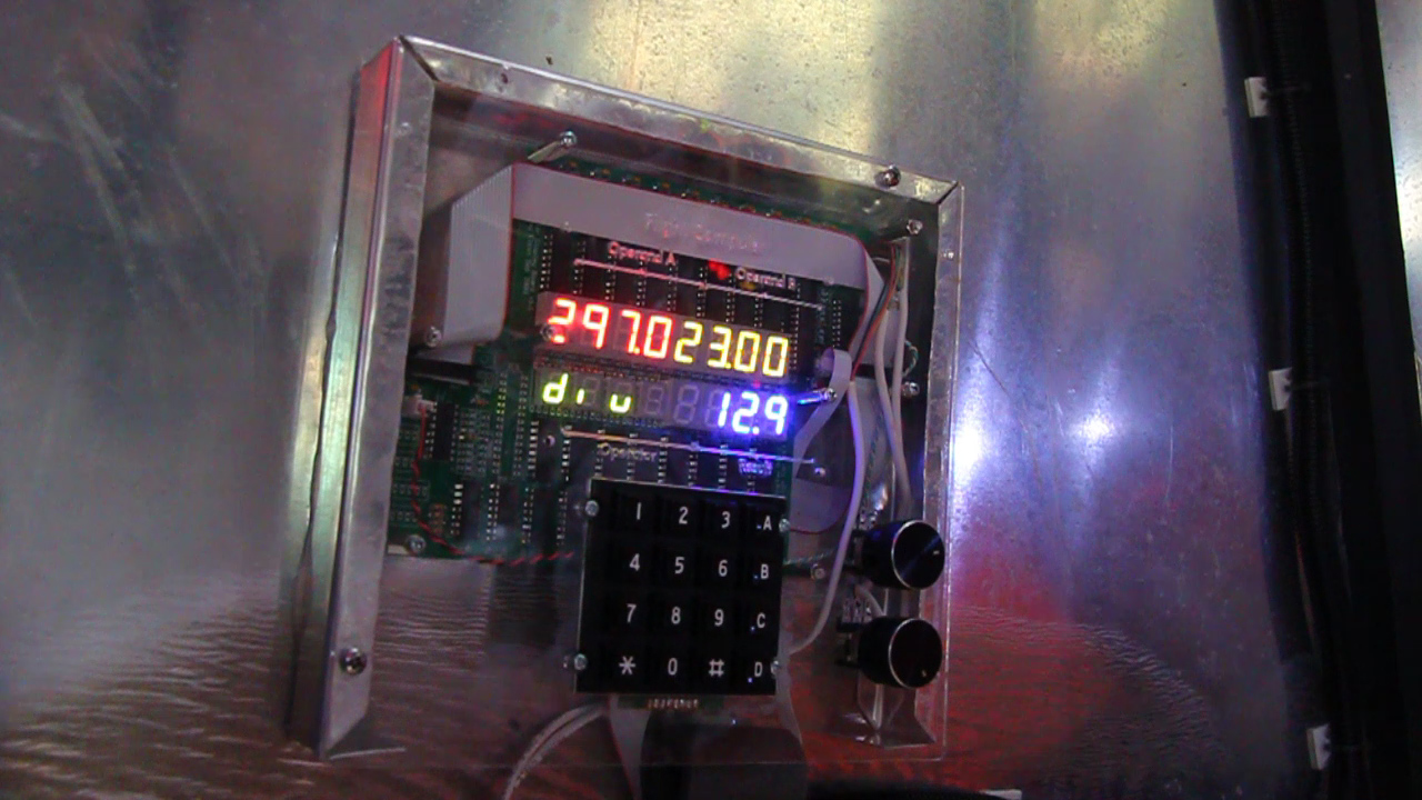
- Calculator The calculator panel (right) has four colored display fields and a keypad. Instead of randomly flashing numbers, we decided to make it a working calculator. The top two fields are the operands, the lower-left is the operation (in this case, "div", for divide), and the lower-right field shows the result. One of the knobs cycles the input focus among the four fields.
- Sound effects Operations that have sound effects, like the takeoff sequence, are generated by a hand-built audio board. It has a processor that can be attached to the rocket's TWI network, an SD card slot, a digital-to-analog converter and an amplifier. Audio sequences are created on a desktop computer (e.g., using Audacity) and written to an SD card. To keep things simple, we do not use a full filesystem. On the PC, a Python script aggregates all the audio clips into a single multi-block image and adds an index block at the beginning that describes each clip's starting block number and length. The image is then written out to the SD card's raw block device. SD cards have simple SPI interfaces, so it's easy for the audio board's Atmega processor, which has SPI support built-in, to read individual blocks without much software overhead. When the SD card is installed in the rocket and the audio board starts, it reads the index block. Upon receiving a sound-effect request message from the primary processor, it seeks the SD card to the start block of the requested clip and streams audio samples off the card and into the DAC. The processor runs at 8MHz, which gives us time to play audio at 16KHz.
The Rocket Operating System
In the earliest prototyping stages, the rocket had no operating system; like most small microcontroller projects, we just wrote code directly against the hardware. It soon became clear that the scope of the software required was going to require something more structured.
Thus was born Rulos: The Ravenna Ultra-Light Operating System. It provides the basic services common to all the software modules: a scheduler, a simple "frame buffer" for the LED panels, a lightweight network stack, and a framework for handling input from all the input devices such as knobs, buttons and the joystick.
Display Software
Rulos includes a layered stack of lightweight UI components to manage seven-segment and matrix LED displays. At the bottom of the stack, Rulos defines a bitmap for each character, and maintains mapping tables that rewrite the bitmaps to compensate for the physical orientation of each panel and of each LED installed in the panel.Above that, board_buffer objects provide offscreen bitmaps for regions of characters. Each software module maintains its own region and draws into it. Board_buffers can be pushed, giving high-priority displays the ability to take over a display area; when the stacked buffer is popped, the lower display is refreshed from its backing store, and further writes from its module are passed to the display. This makes it easy to create the LED equivalent of modal dialog boxes.
An alpha mask allows a module to claim subregions of a physical display. The calculator, for example, uses a data-entry cursor whose size varies according to the selected field. As the cursor is moved, the module pushes its board_buffer region onto the appropriate part of the display, using the alpha mask to limit its opacity to the field being highlighted.
A string library maps ASCII characters to 7-segment bitmaps for alphanumeric displays. A scrolling text module enables output of long messages on the constrained display surfaces. The large multifunction display is used for long alphanumeric messages, but also for raster graphics: Another module provides a raster interface to the display's segments. The docking mode, for example, plots circles and axes, while the launch mode countdown timer blits constant sprites; each calls the raster library's point-drawing functions on a 32x24 bit plane. Of those 768 points, 1/3 map to the 256 LED segments, and the other 2/3 are treated as "dead pixels."
The entire stack of software, from bitmaps to overlapping-region windows and a raster graphics renderer, runs comfortably on 8-bit devices with 2K of RAM, leaving plenty room for application code.
Input devices
Rulos also supports a variety of user input devices, from pushbuttons and knobs to 16-key keypads and joysticks.Keypads generally have 8-wire interfaces: one wire for each row and column. When a key is depressed, the corresponding row and column lines are connected. Our display panel has an optional 8-pin header that can be populated for attaching such a keypad. The Rulos keypad module periodically scans the key matrix, debounces the buttons, and manages a keystroke buffer that can be read by applications.
Vintage analog PC joysticks also have simple electrical interfaces. They have two linear potentiometers, each of which vary between 0 and 100K ohms as the control stick is moved through its range of motion in the X and Y axes, respectively. The RULAV panel has an optional joystick header that connects the potentiometers to a voltage divider and two of the analog-to-digital converters on the Atmega processor. The Rulos joystick library samples their values every 10msec, applies a moving average and thresholds the average with hysteresis. It also monitors and debounces the joystick's "fire" button. All of this state is available to applications.
User-input events
Rulos incorporates a flexible, polymorphic user-input event model, a pared-down version of the design pattern used in conventional desktop user-interface software. Discrete input events from diverse devices, keypads, buttons, and detent knobs, are routed through an event queue. Applications also enqueue synthetic events to order them with respect to user input.Input events are distributed across the network. Each panel with input hardware runs an event-forwarding module that registers to receive events and forward them on the network; a corresponding module on remote panels injects each event packet into the panel's queue.
User attention is managed with a pared-down "focus" mechanism that also mimics the desktop window focus paradigm: application modules accept and delegate focus through the UI event queue, and use display feedback to inform the user where input events will be directed. Focus configuration is also forwarded across the network.
The resulting framework arranges that neither input events, nor focus ownership, nor display output is bound to any given panel. The rocket's software exploits this decoupling property, with input coming from multiple panels, application-level modules processing that input (according to modal focus) on different panels, and output being directed across different panels.
Timers and Scheduling
Event-driven programming is central to embedded systems software. Most Rulos programs are heavily event-driven; consequently, much of our work in Rulos has been in developing a flexible set of timing and scheduling primitives. The problem is made interesting by the wide range of requirements placed on timers by applications. The graph to the right shows the periods of tasks in the rocket, ranging in frequency from the length of a single audio sample (80usec) through tens of milliseconds for real-time actuators and animated displays, to seconds for controlling modal user input interactions. In addition, the underlying hardware has timers with a range of capabilities. The Atmega processors used in the RULAV have both 8-bit and 16-bit counters that can be used to generate timer interrupts. Our goal with Rulos was to make it easy for developers to match available hardware resources to their applications' requirements.
Mininmum, mean, and maximum scheduling periods for 23 unique tasks in the rocket software.Task execution in Rulos can be scheduled in one of two ways: the heap scheduler, a full-featured real-time event manager, and a hardware timer, an interface to underlying hardware interrupts with a minimum of software interposition.
Hardware timers and quantization
Microcontrollers typically have a variety of hardware timers of different sizes (e.g., 8-bit, 16-bit). Each can be configured to tick at an incomplete range of discrete values which are integer divisors into a frequency reference. The reference can be the processor's clock or an optional external oscillator. The Rulos platform definition for each processor describes the hardware's range of available timer widths, clock frequencies, and clock divisors. These hardware properties generate unpredictable quantization constraints on the available clock periods, which Rulos hides from the application.When using a hardware timer, a Rulos application specifies which timer to use, the value of the optional time base, and the desired interrupt-generation period. Rulos enumerates all of the available prescaler values, selects the smallest prescaler such that the timer resolution spans the jiffy period, then selects the timer compare value to produce the maximum period less than the requested period; that is, the output frequency is never less than the requested frequency. The actual jiffy period is returned so that a higher layer can properly maintain a count of total elapsed wall-clock time.
Hardware timers are low-overhead, and low-jitter because they run at interrupt time. This makes them most appropriate where a single task must be executed frequently and should preempt other activities in the system. We have used hardware timers to drive servos and synthesize waveforms in the audio board. However, they do not readily scale to a system with many tasks---a case handled better by the Rulos heap scheduler.
The Heap Scheduler
The heap scheduler is used by most Rulos applications. It provides a flexible and scalable way to schedule future events over a wide dynamic range of periods. When the application starts, it can instantiate a heap scheduler on any available hardware timer with any scheduling quantum over about 200 microseconds. The actual jiffy period is recorded in the scheduler, so that a system clock value can be maintained in wall-clock microseconds (to the accuracy of the base oscillator). The clock is represented by a 32-bit value in microseconds, which rolls over every 1.2 hours. The heap comparator divides time into past and future epochs of 36 minutes each, so that any task scheduled at a rate faster than about 30 minutes never needs concern itself with clock rollover.Applications can call the Rulos schedule() function to schedule a task execution for the future. Rulos maintains all active tasks as a heap with real time of next execution as the key. Both sleeping and runnable tasks occupy the same heap: a task is runnable if its due time is in the past epoch. To schedule another task for "now", it is simply inserted with a key matching the current clock; it will run in the current jiffy immediately after all other runnable tasks complete. A task scheduled for a second or a minute in the future will stay out of the way as other tasks run thousands of times, and then start right on schedule. The scheduler runs user callbacks outside of interrupt context, so they are pre-empted by tasks running from hardware timers.
The resulting memory-friendly scheduler has a very simple structure, yet neatly interleaves a wide variety of tasks at multiple time scales while maintaining consistent soft real-time scheduling goals. Each task switch costs O(log n) for heap pop and insert operations. A CPU monitor module tracks idle time while waiting for tasks to become runnable, and measures the CPU busy fraction, facilitating detection of expensive tasks on real hardware.
Every time the underlying timer ticks, each task's deadline is advanced, and any that have arrived are executed. That is, with n tasks in the system, the Rulos scheduler performs a constant-time operation on every processor tick and an O(log n) operation on every task execution or new task scheduled. Thus, Rulos maintains asymptotic efficiency for systems with a large number of tasks, and substantially wins when many of those tasks have long periods relative to the jiffy. Given the relative expense of 32-bit operations on 8-bit platforms, an efficient scheduler turns out to be surprisingly important.
Network stack
The primary pressure on Rulos' network stack is memory. So far, Rulos applications have escaped the need for dynamic memory allocation, and hence the need for reasoning about out-of-memory conditions. As a result, Rulos modules must preallocate network buffers. Each module wishing to listen preallocates a buffer, fills it in as a prototype to indicate destination port, available capacity, and receive handler, and registers it with the network stack. Upon message receipt, the network stack populates the buffer's payload and queues the handler. The application module services the message, then returns the receive buffer to the network stack to listen for the next message. During the service interval, the network port is closed unless the module specifically registers a second buffer to absorb more messages.Sending packets is symmetric. A module preallocates a send buffer. When ready to send a packet, the module fills in the payload, updates the destination, marks it busy, records a send_complete callback, and registers it with the network stack. The network stack uses the media layer to negotiate the channel. The media layer holds the buffer while its interrupt handler drains the bytes out one-by-one. Upon completion, the network stack calls the module's callback, which typically marks the buffer free for use in a later transmission.
We experimented with a zero-copy network stack, designed to deposit each incoming packet directly into the appropriate listener's receive buffer, avoiding the need to allocate a first-stop buffer of maximum size. Our experience showed this software architecture to be quite brittle, especially around timing variations.
Therefore, the present stack does employ a first-stop buffer. Only once the entire packet is received is it decoded, checksummed, demultiplexed, and copied into the application buffer. It comes at a non-trivial RAM cost, doubling the cost of the maximum application-specific buffer, but that cost is worthwhile: once we adopted the approach, the network stack became extremely robust, even as we added new media layers below.
The rocket application uses five network ports on its two node types, for transmitting user input events, actuator status events, and audio and video user interface synchronization events.
RULAV Simulator
A key aspect of RULOS is its RULAV hardware simulator, which lets us develop and debug software on the PC, without any of the rocket hardware. We originally wrote it because we wanted to start writing software long before the hardware was assembled. Even now that the hardware is finished, the simulator gets frequent use; code is much easier on a desktop PC than in a cramped, cold, rocket on a rainy Seattle night. Creature comforts aside, PC simulation has a full development environment at its disposal, complete with a gdb and console for printing debug messages. Software running in the rocket has no "console" other than its LEDs, which are less convenient.To implement the simulator, we split RULOS into two parts: hardware-dependent and hardware-independent. The hardware-independent parts have functions at higher levels of abstraction: "Turn on the LED on Board 4, Digit 1, Segment 3." The hardware-dependent functions do the work of twiddling the bus address and data lines to send commands to the LEDs' latches. When we build RULOS in simulator mode, a simulator module is compiled and linked in place of the hardware modules. The simulator implements the same functions as the hardware module, but (for example) draws a segment on the PC screen using the curses library instead of physically manipulating hardware control lines. The colors of the simulated LEDs are configurable so they match the rocket hardware. The simulator also lets us use the keyboard to simulate inputs from the ADC, joystick, knobs and keypad.
The screenshots below show our original digit-test program (left) and a test of the complete rocket software suite, mid-countdown (right).


- Calculator The calculator panel (right) has four colored display fields and a keypad. Instead of randomly flashing numbers, we decided to make it a working calculator. The top two fields are the operands, the lower-left is the operation (in this case, "div", for divide), and the lower-right field shows the result. One of the knobs cycles the input focus among the four fields.