Electronics
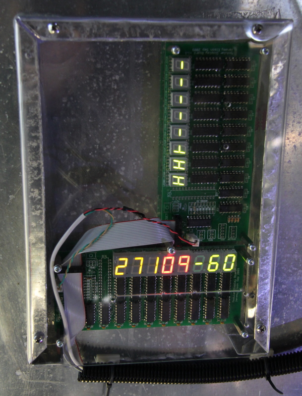
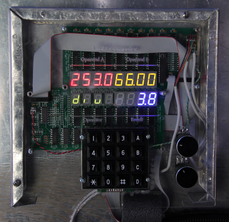
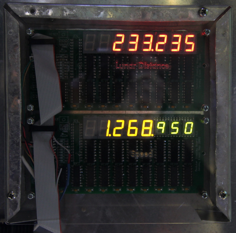
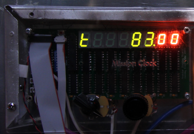
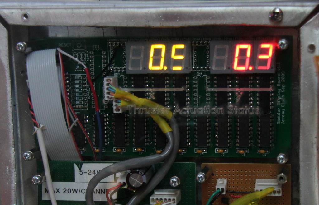
The heart of the rocket's control system is the RULAV Display Panel, which we designed specifically for the rocket. Most panels in the rocket are copies of this board.


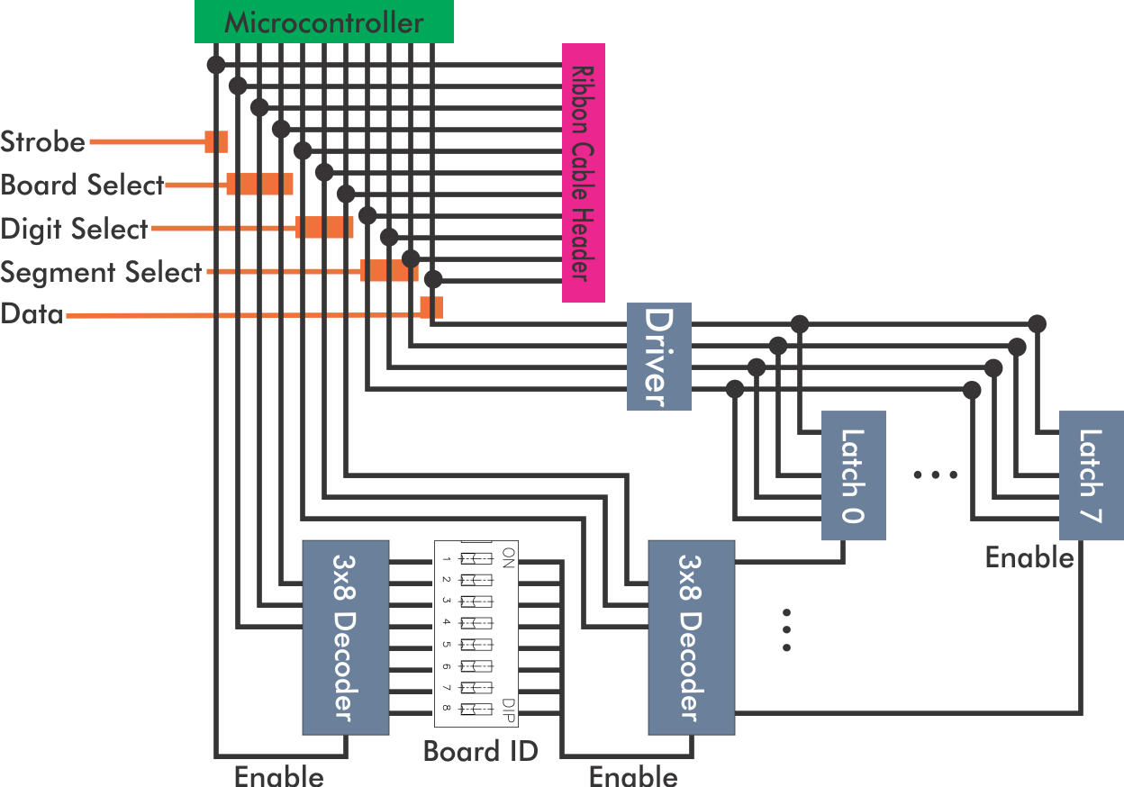
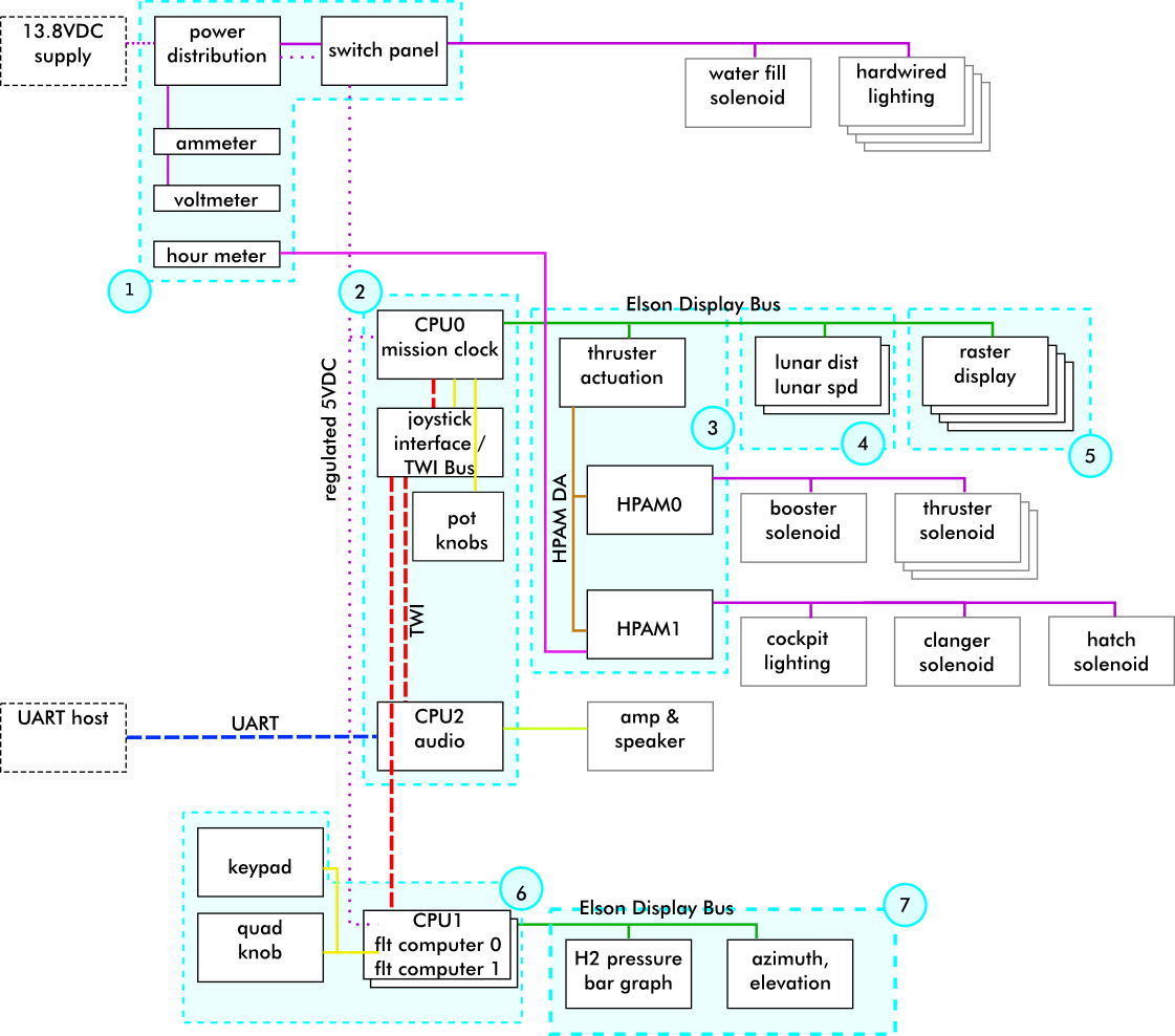
The 8-board limit didn't seem relevant when we first designed the panel, but as our ambitions grew we realized we actually wanted a total of 12 panels, and more knobs than could be read by the ADCs on a single processor. The final design uses two board busses, each controlled by a separate processor, and a TWI network between them. The panels have a variety of digit colors and sizes:

The HPAM: High Power Actuation Module
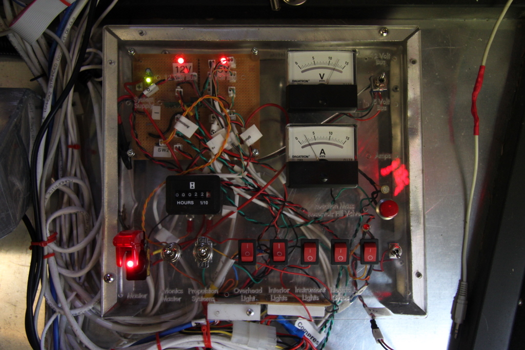
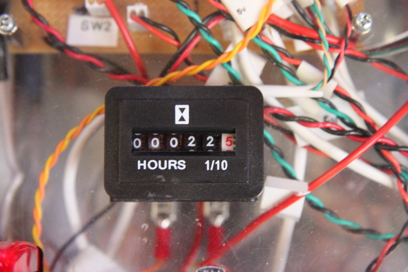
The rocket electronics primarily run at 5V, and the microcontroller and latches can only source about 25ma per pin. The rocket has devices that need higher currents and voltages, but that we'd like to switch on and off under software control: overhead lights, solenoids, and Hobbs meter. These all run at 12VDC and need up to an amp. To control them, we hand-built two special boards, each of which has 4 individually controllable 30-amp MOSFETs. Each channel has a red status LED and a flyback diode to prevent voltage spikes when switching off inductive loads, like the solenoids. The MOSFET gates can be attached to the latch outputs of a display panel. We call this type of board an HPAM, or High Power Actuation Module.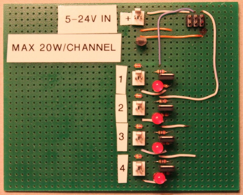
Thruster Control
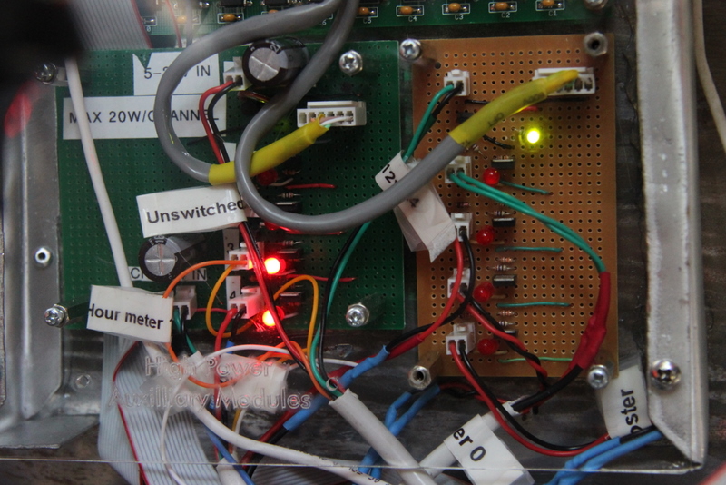
The three thrusters and paint-shaker are powered by compressed air. The processor can turn each device on and off by sending a control signal to the HPAM, which sends current to one of four electrically actuated solenoid air valves.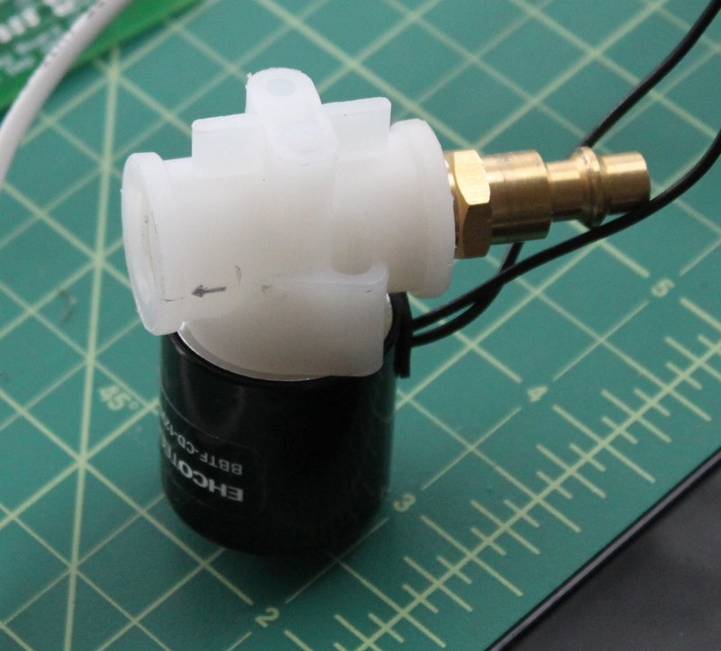
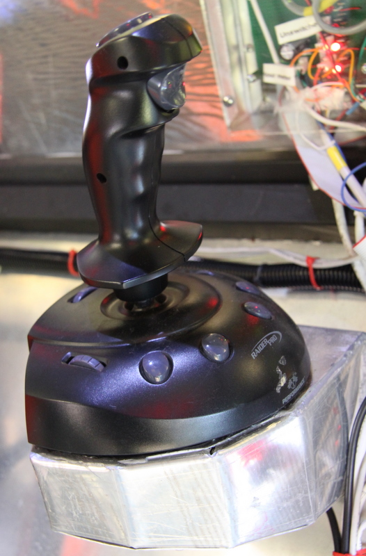
The joystick is a vintage PC joystick with a 15-pin game port interface. Such old beasts have simple electrical interfaces: two linear pots, each of which varies between 0 and 100Kohm as the control stick is moved through its range of motion in each of the X and Y axes. The output of these pots is connected in series to a voltage divider, with one of the Atmega's ADCs reading the middle voltage of each. The fire button is a simple switch that is connected to ground when depressed; this is connected to a spare GPIO on the Atmega, which has an internal pull-up resistor.
Power Distribution
12VDC power comes in from the house via an underground trench, arriving at the RULAV Power Distribution Panel. The board contains a switching power regulator that is configured to produce 5V. Both the 12V house power and 5V regulated power are exposed on a dozen 0.1" headers we use as power connectors.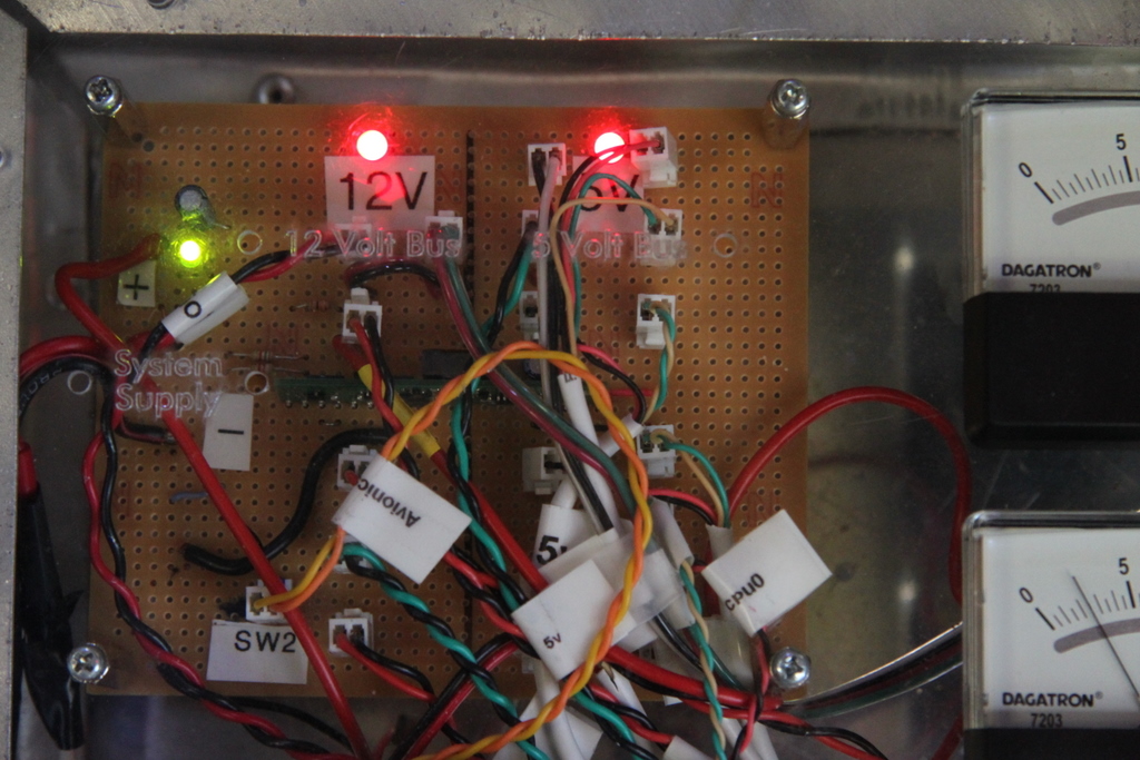
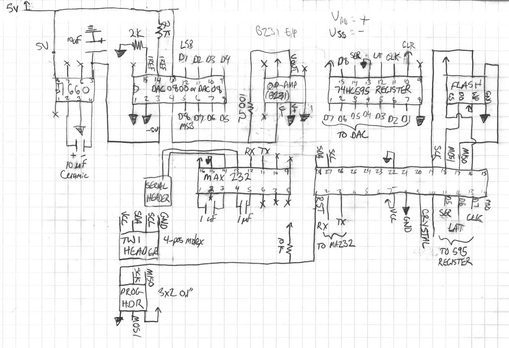
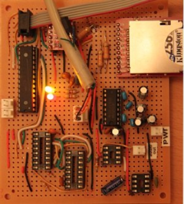
Audio
To give the rocket a more authentic feel, we added an audio system that plays pre-recorded sounds during events such as takeoff and docking. It consists of a simple "sound card" we built ourselves connected to off-the-shelf PC speakers and a powered subwoofer.Our audio generator board is another hand-built board with an Atmega328 at its core. The analog side consists of an 8-bit digital-to-analog converter (DAC08), a '595 serial-to-parallel shift register, and a garden-variety op-amp. The op-amp gain is configured to produce 3.7v peak-to-peak, centered at 0, which seems to be the standard line-out voltage range from a PC according to our tests. The audio clips are pre-mixed and stored on an SD card, read using a Sparkfun SD card slot wired to the SPI pins of the Atmega328. The audio board's processor is also attached to the inter-panel TWI bus so it can receive audio play commands from the processor running the main rocket software. (Our software page describes this process in more detail.)