Mechanical Design
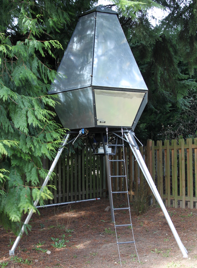
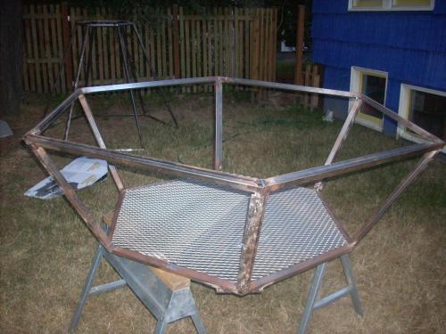
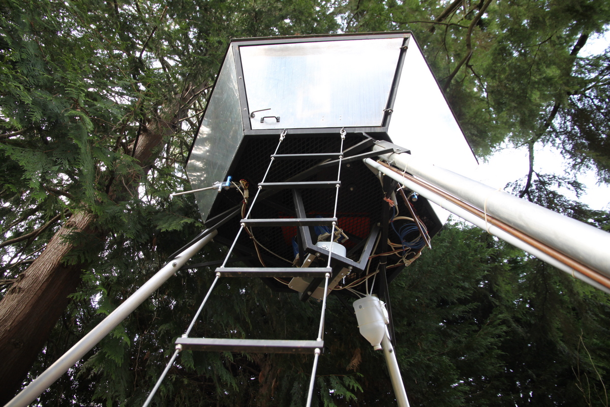
The rocket's cabin is composed of three segments, each with a hexagonal cross-section. The widest hexagon is 2 m across at its widest point. The cabin is 2.3 m tall.

Planning for assembly
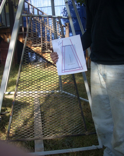
The design calls for creating in-plane quadrilateral surfaces on the metal frame, so that each aluminum panel can be riveted along all of its edges. Square tube makes for easy welding, because straight cuts make ready joints. Each face of the cabin has three tubes in plane, and then borrows its fourth edge from the neighboring face; I welded on a flat strip of steel to provide a fourth planar surface to which I could rivet the skin.Prototyping in paper
One challenge was figuring out how to cut the correct angles on the ends of the tubes. I'm pretty good at working out the side-length trigonometry for the wire frame, but those compound angles really made me dizzy. I had a bill-of-materials spreadsheet that converted coarse measurements ("bottom segment has radius 24 inches") into lengths and quantites of square tube. I extended it to also tell me what compound angles to cut on the end of each tube.
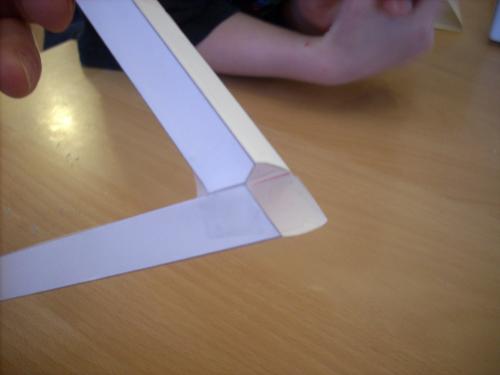
The math was hard enough that I was still unconvinced that it would work on real metal, so I then built a little python script that simulated the effect of each cut on the miter saw, and emitted a PostScript page that cuts and folds into a paper model.
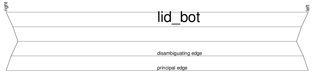
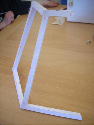
One tube on each face requires two compound cuts on one end, to provide clearance for the bottom edge of the adjacent face. The math was indeed hard; the paper models showed an error on pretty much every step.