Mechanical Assembly
Assembling a rocket often requires special equipment. We didn't have it as bad as some. But there were plenty of problems to solve, even after trying to design for “simplicity”.Compound angle cutting jigs
I dropped a couple hundred bucks on steel at Everett Steel. I suppose this is a good place to go if you're, you know, some sort of industrialist who actually builds things with steel. The guy behind the desk always seemed to be "swamped" with work, in a union-employee sort of way that meant he could talk to me for 10-15 minutes about why he hadn't even pulled my order off the teletype yet. The yard guy, on the other hand, was much cooler; I think he enjoyed the absurdity of putting a few hundred pounds of steel on the roof of my Ford Escort and watching the suspension droop.
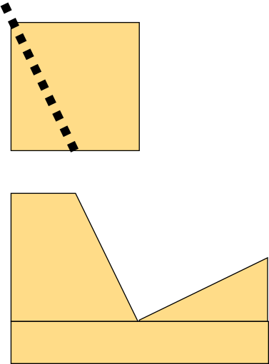
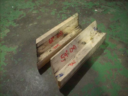
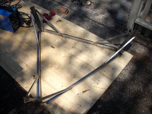
Cutting the compound angles was itself a trick, since my Harbor Freight metal cutoff saw offered only a simple miter fence. I solved this by building tilt jigs. I computed the compound tilt angles I'd need, collapsing a few close angles together. The angles came in complementary pairs, since the miter fence has a reasonable range of +/-45 degrees, but tilting can easily pass through all 90 degrees. For each of the four complementary angle pairs, I set the table saw tilt to the smaller of the two angles (that is, the one the saw could tilt to), and ripped a strip of 2x2 lumber so that the saw came out through the corner. The two strips could then be glued down to a flat strip of wood, leaving open a right angle tilted at the requisite angles.
Breaking steel
I built the lid layer first, because it was the smallest, least
sensitive to sloppy construction, and wasted the least steel if I
blew it.
I didn't quite blow it, but it certainly didn't come out very straight.
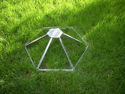
From the twisty construction of the lid, I understood my mistake. First, I'd established the angle between the edges on each individual face just by the miter angle cut into the tubes. There was enough error in this angle that, once welded, it was impossible to assemble the final 3D structure to the right shape. Second, it was hard to even hold the six faces together long enough to tack weld them; just too many moving parts. Magnets were no help, since the tubes were never coplanar or perpendicular.
Construction jig
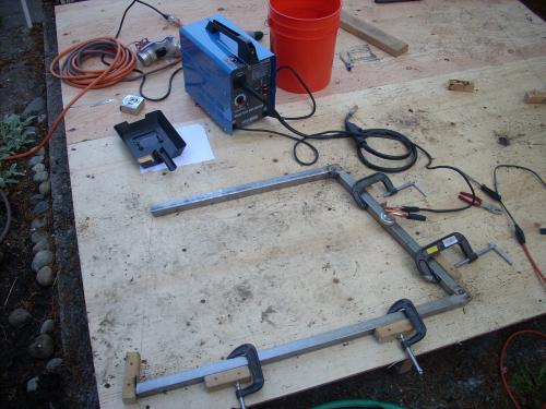
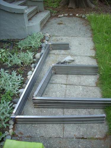
So, for the next section, the lower section, I built an 8x8 platform from a couple pieces of plywood and some studs. I screwed pegs down to the panel to make a jig, holding each tube at the precise final-assembly angle, and tack-welded them in place. (I did more than tack weld, until I realized that the smoking plywood was probably interfering with the weld quality.)
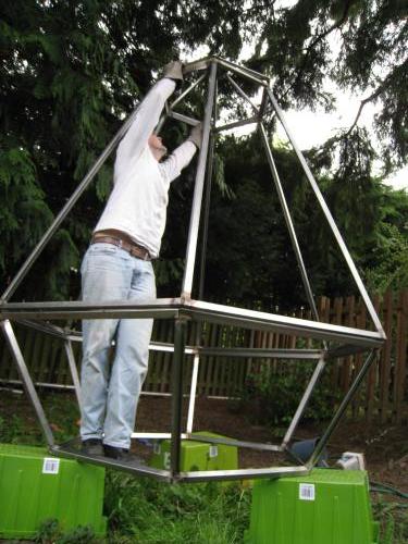
Assembly
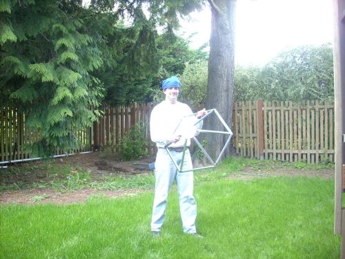
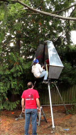
Then, to solve the challenge of holding all six pieces in place simultaneously, I laid out the hexagonal base of the prism on the plywood platform, screwed in pegs around the perimeter, and propped the C-shaped faces up in the hexagon. This worked much better than trying to freehand 30 degrees of freedom. Imprecision made it inclined to pop out of shape, but my friend (no, not the first-grader pictured here) stood in the middle to hold things in place while I tacked the joints. With the jigs, the assembly came together quite nicely.

Hatches
Next was manufacturing frames for the door and window hatches, and hinges for those and the lid hatch. This took longer than you'd think for the amount of metal involved. The 13 mm steel rod I used for hinge pins cause two kinds of trouble. First, here's a tip when drilling: clamp that metal down really well, or you'll blast lots of drill bits apart. Second, my little 1500W welder had a tough time heating up rod that thick before it had made a mess of donor metal; preheating the rod with a propane torch helped greatly.
Gantry
Then I turned to the "gantry", the triangular pyramid that holds the rocket high off the ground. Before welding, I match-drilled each steel angle to a leg, a 2.3 m length of aluminum tube. The biggest trick, again, was building alignment jigs on the plywood platform to hold the tilted members in place while they're tack welded.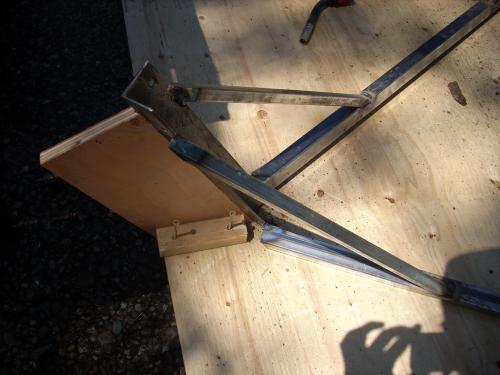
Load testing
I climbed up on the assembled gantry, and it was pretty solid. If I shake vigorously, I can get the aluminum tubes to wobble a little, but the geometry makes it pretty difficult to put them out of column or make them buckle. I think this is pretty much how NASA designed the Gemini vehicles: they'd weld something together, and then an engineer would clamber on top, wiggle around a little, make some erudite comments, and pronounce it flight-ready.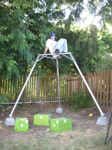
Cabin floor
Jeremy found me some cutoffs of thick expanded steel for only $40 on craigslist. The guy was in Bremerton, but no problem: Jeremy also flew me over to Bremerton airport (KPWT) in his Cardinal. We wrapped the steel in a tarp to avoid snagging the plane's upholstery, and flew it back home. Dreamlifter!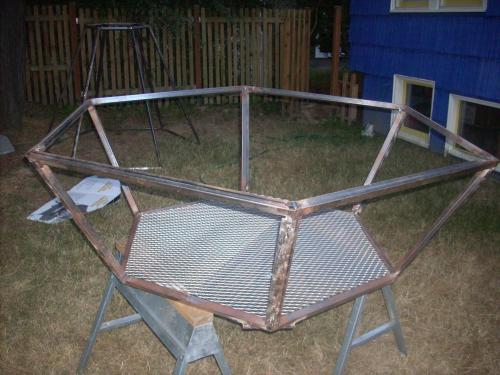
Window screen
The window face opens 2.7 m off the ground. It's protected by a 3/4" steel frame containing a panel cut from the last sheet of expanded steel (use the whole buffalo, I've always said).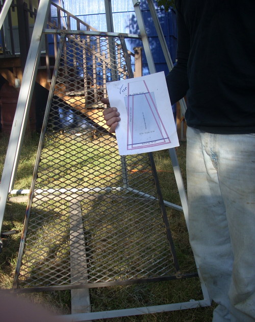
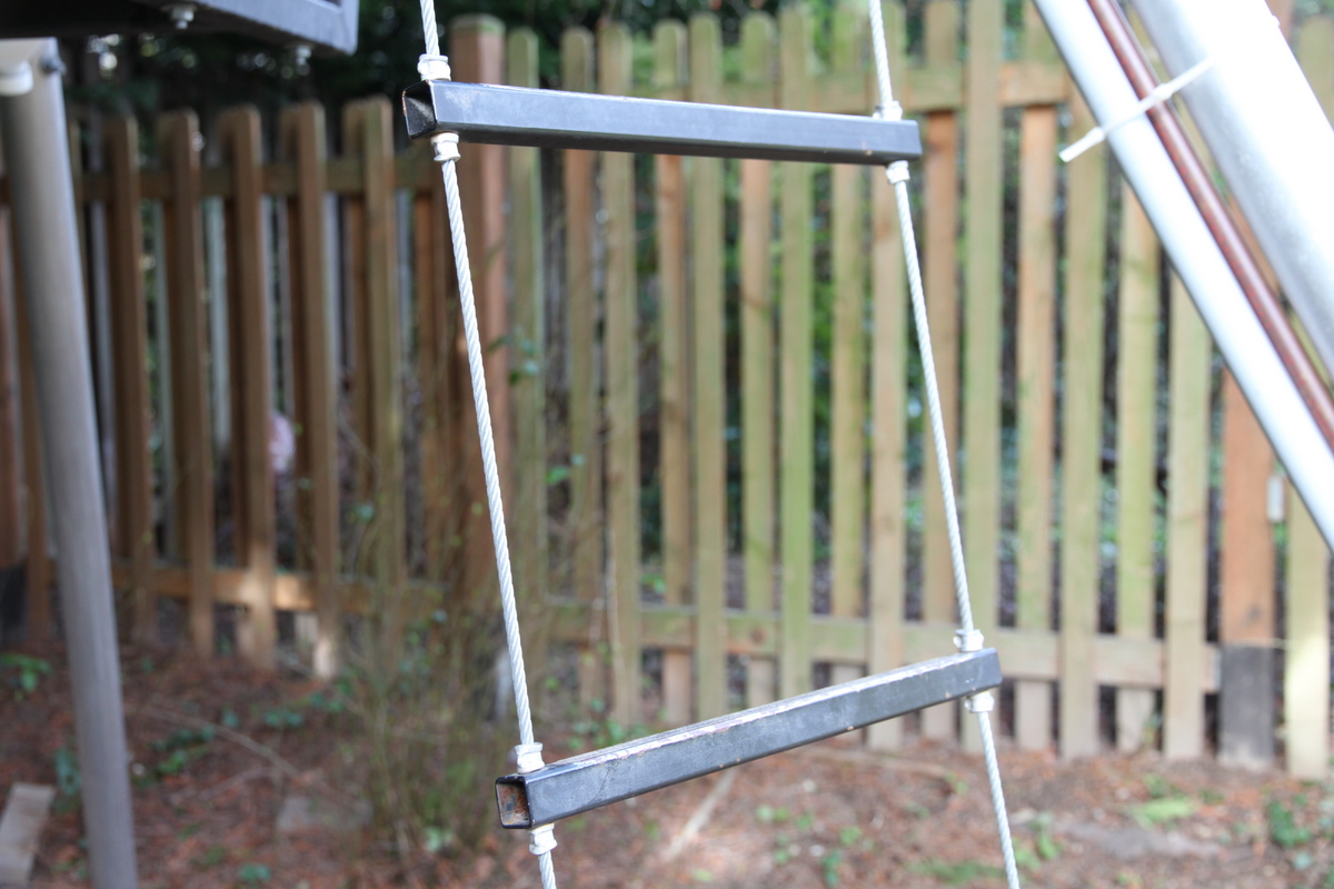
Entry rope ladder
Entry is via a stainless-cable rope ladder.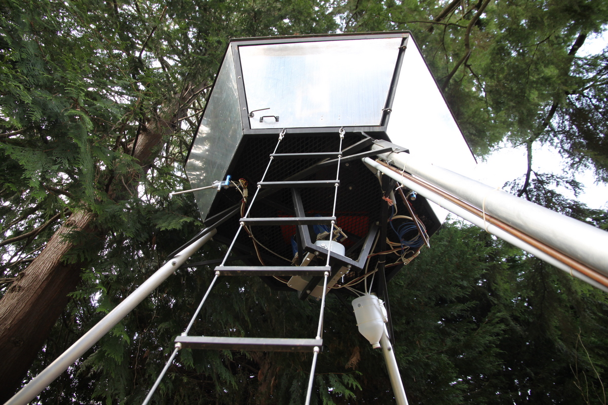
Paint
A friend of ours is a professional aeronautical chemist. He designs the paints and coatings that stick to Boeing jetliners. We didn't ask him for advice. Instead, I sprayed quart after quart of Rustoleum onto our airframe.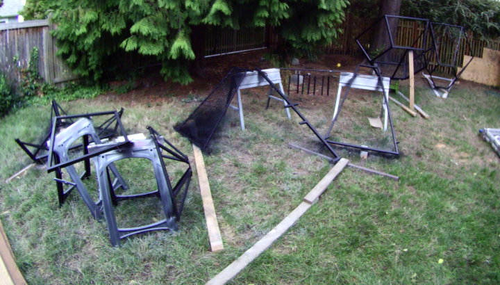
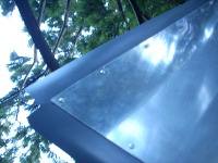
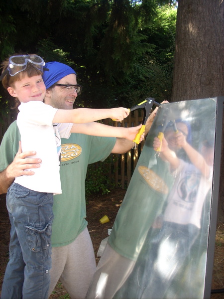
Skin
The vehicle is skinned in sheet aluminum. Cutting, welding, and grinding steel weren't tasks I felt comfortable sharing with my six-year-old. But drilling and pulling pop-rivets sure was!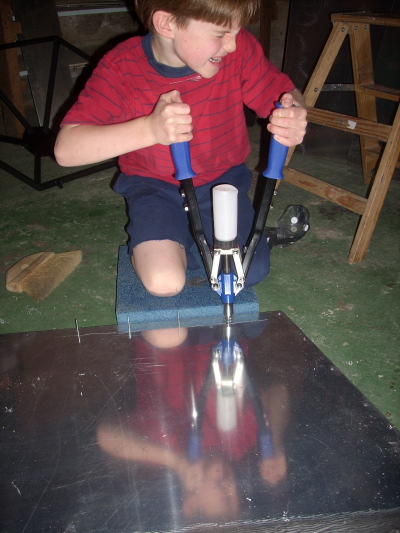
Engine mount
Would you believe we have another friend whose day job is to ensure that the engines stayed attached to the Boeing jetliners? Our treehouse has the same problem. This bracket bolts on below the cabin to hold the main “booster engine” (see Pneumatics section).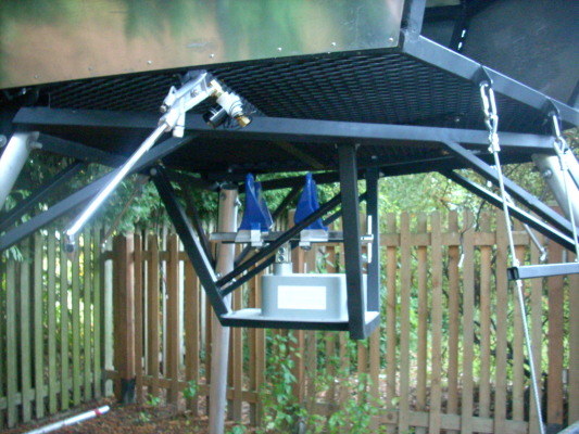
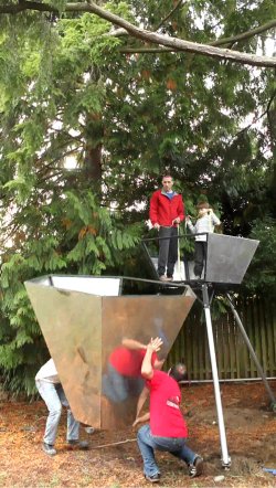
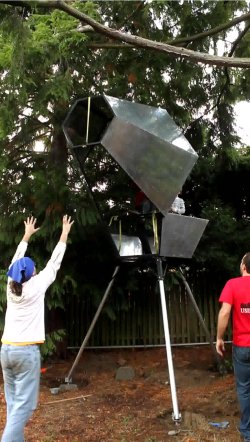
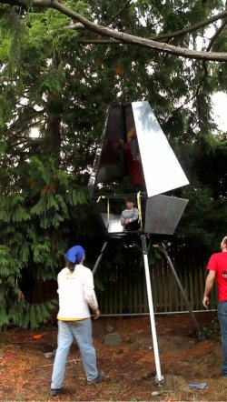
Fuselage assembly
It was challenging to assemble this 4.6 m tall monstrosity without the benefit of a Vehicle Assembly Building, or really even a small crane. Jeremy and Alex came to help with an old-fashioned community rocket-raising.First, we bolted the legs to the gantry and gantry to the lower half of the cabin. We righted that contraption, and bolted each leg to a buried concrete footing. Eliot and Alex climbed up into the half-cabin. Jeremy and I inverted the torso section, and held its open edge up to a matching edge of the hip section. Alex and Eliot turned a couple straps into an ersatz hinge. Jeremy ran a strap from the inverted top of the torso up to Alex. Jeremy and I swung the torso halfway up, so that it was lying sideways, then Alex pulled his strap to right it the rest of the way. We hacked a few cedar sprigs out of the way, and bolted on the torso.
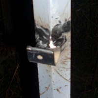
We hung the entry, window, and lid hatches and cotter-pinned them in place.

Weatherstripping
I designed the cabin with some attention to overlaps, to ensure that rainwater poured over the skin, rather than into the interior. Still, I needed to add some PVC strips to the hatch and upper window to finish the job.