|
|
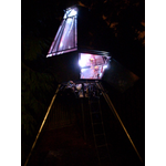
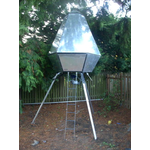
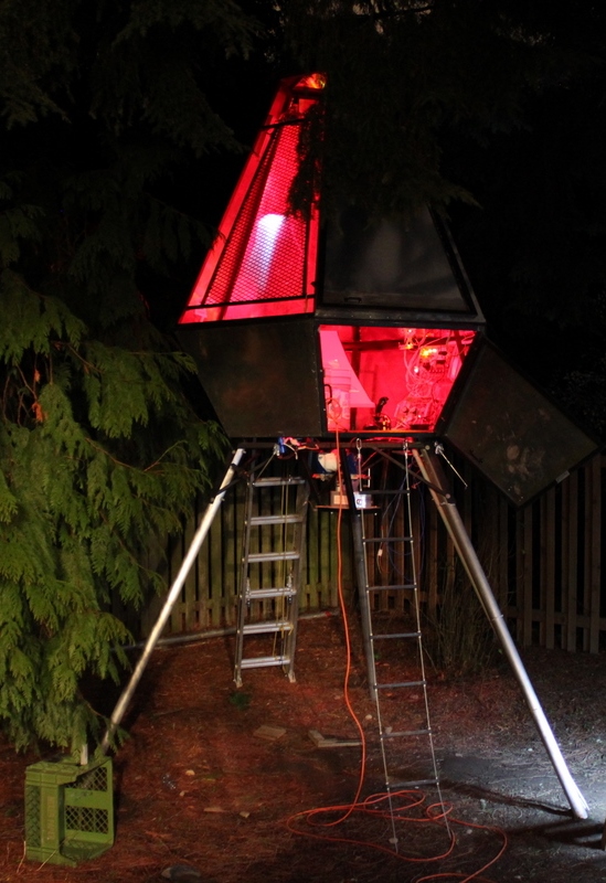
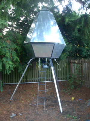
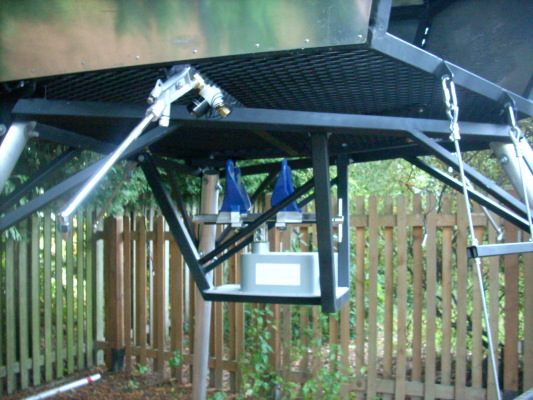
The Ravenna Ultra-Low-Altitude Vehicle is a treehouse equipped to explore the lower frontier of the troposphere.
Read: in chronological order newest entries first Read about: All entries Jon's build log Jeremy's electronics log Grandma Jan's flight suit |
|
None
                                                                              |
atmega flashcard toy Saturday, January 22, 2011 -- jonh
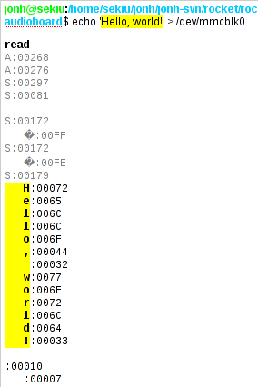
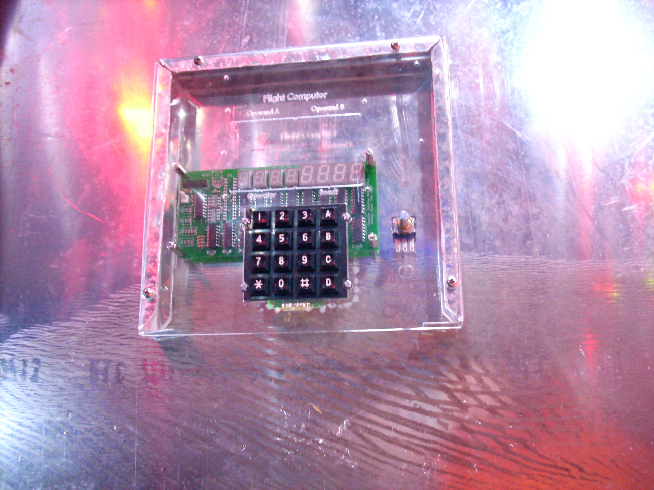
So a few other electronics treats have shown up. Jeremy and I discovered the Atmega 1284, equipped like our workhorse 328, but in a 40-pin through-hole package with a metric boatload of RAM and program flash. I also grabbed a $4.50 LCD screen from eBay. As an excuse to play with them, I came up with this little toy for Eliot.
connected to rocket Sunday, December 19, 2010 -- jonh
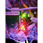
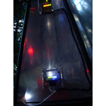
Today was different. There were some false starts: I needed to add a power cable to the rocket, and I spent a long time with an oscilloscope and a spare rocket board discovering that I'd just failed to set the audio board's network address (blush). But at 10pm, I went out to the rocket with a pair of headphones and the audio board, and plugged it in. When I turned on the master switch, I got the splash screen ... and a quindar tone! (A quindar tone is the beep that started and ended NASA Apollo transmissions. They were only heard by the viewing public, not the vehicle crew, but they're now so iconic that the R-ULAV is going to use them whenever possible.) Pong beepend and booped exactly as expected. And when I started a launch, the Apollo 11 countdown played in perfect synchronization with the giant rolling digits. Success!
audio is streaming Saturday, December 18, 2010 -- jonh
 software running software runningTuesday, December 14, 2010 -- jonh
 audio breadboard running audio breadboard runningSunday, December 12, 2010 -- jonh
 audio board protoboard audio board protoboardSaturday, December 11, 2010 -- jonh
 audio board breadboard audio board breadboardWednesday, December 1, 2010 -- jonh
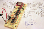
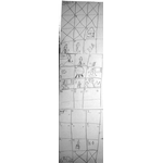
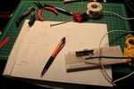
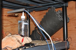
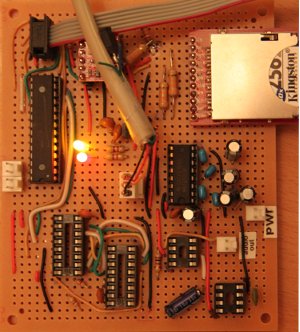
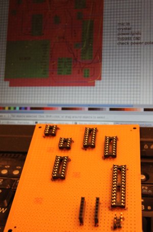
So I sat down to begin prototyping an audio board. I got partway through, and fired off a long list of questions to Jeremy. Jeremy pointed out that he'd already breadboarded much of the design last year. And hand-sketched it up on a sheet of graph paper. And scanned it. And checked it into the rocket source code repository (photo background). And maybe I ought to start with that. Armed with his schematic and recently-arrived Sparkfun and Digikey orders, I prototyped the 3.3v conversion and SD slot, the pieces that Jeremy hadn't yet prototyped. To be able to learn anything from the prototype, I included a CPU, programming header, MAX232 and RS232 serial output port. The only thing missing now is (a) software to talk to the SD card and (b) a serial port. I forgot that modern laptops don't have serial ports, so it's time to find a USB-serial dongle.  new firmware; repairs installed new firmware; repairs installedSaturday, May 1, 2010 -- jonh
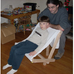
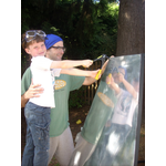
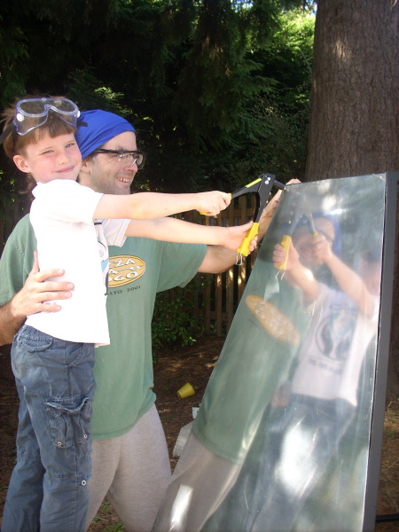
Today I got out to the rocket with Eliot and his friend. We installed the repaired HPAM and fixed a wire splice that got broken during the Great Wire Bundling. We chose a few nice knobs for the pots and quadrature encoders, took them back to the shop to drill them out to the right diameter, and then installed them. I uploaded the new software. I noticed that uploading on rocket1 is flaky; that's the CPU whose programming port doesn't have the bus isolator. The second quad knob didn't work immediately; I'd put the ground pin on the wrong side of the connect. The potsticker code had a bug or two that I diagnosed from the orange couch. One quadrature knob and one pot are working correctly, and now Eliot can play Pong with round knobs, as it was meant to be. I sped up pong a little, and tuned the response rate on the knobs. I arranged for the second pot to tweak the lunar velocity display. I also noticed that, if you bump the programming header into the rocket's aluminum skin, it gives off awesome sparks! Oh yeah -- 5V. I should insulate that.
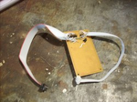
repaired HPAM; new knobs Saturday, April 24, 2010 -- jonh
Jeremy and I discussed the possible causes at great length: did we use the wrong diode to protect the MOSFETs, and induction voltage spikes cooked them? Why both at the same time? We came up with a bunch of theories, and Jeremy gave me a little baggy with some better-chosen diodes and spare MOSFETs, plus advice to inspect the copper traces carefully. I poked at the board for a half an hour, replacing out the channel 3 diode and MOSFET. Things didn't get better. I poked at it some more with a voltmeter, trying to compare its behavior to the working channel 1. The indicator LED wasn't even working; could it have failed, breaking the circuit? I eventually noticed that one of the cuts in the protoboard went a little too far across a neighboring trace. It looked like a mere scratch in the copper, but the ohmmeter showed otherwise. Sure enough, bridging the scratch with soldered cured the board. Apparently there had been just enough copper there to conduct a little current through the LEDs, but even the 10mA of current was enough to heat it up and change its resistance it so that it no longer conducted enough current to light the LED. After that minor victory, I also gathered up the two quad encoder knobs, used a couple LEDs to figure out their pinouts, and made pigtails to connect them to the CPU1 board. 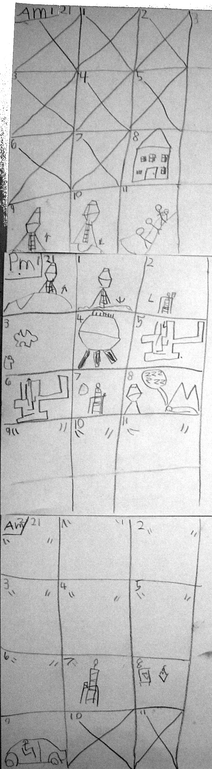 birthday schedule birthday scheduleFriday, March 19, 2010 -- jonh
Ha ha ha! No, son, feature creep must run its course! But it's finally done, or done enough to have a party. Eliot made up this schedule for a birthday party that involves a rocket trip to the moon, a rocket puzzle, and of course a rocket cake. 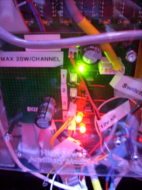 hardware fixed hardware fixedThursday, March 18, 2010 -- jonh
The first problem wasn't a big deal, because processor would turn on the hobbs, reset, then proceed normally; it wouldn't reset unless it went idle and then woke back up. The second problem was even less worrisome: everybody agreed that the little blasts of thrust kind of added to the liftoff sequence. But it still bugged me that there were (probably electrical) problems; I wanted to fix them, and then put the random blasts back, in software. This morning, I got out to the rocket and soldered in some big (2200µF) caps on the lighting and hobbs busses. My "clever" wiring carried only the switched ground back to the outgoing circuits, so I also added separate +12 wires. I think the caps were the important part, but both bugs are now gone. I also terminated the audio board and added a header to the power distribution board to power it. Now the speakers pop when the rocket is turned on, and hiss out a little noise. Jeremy's still building the board that produces the audio signal. 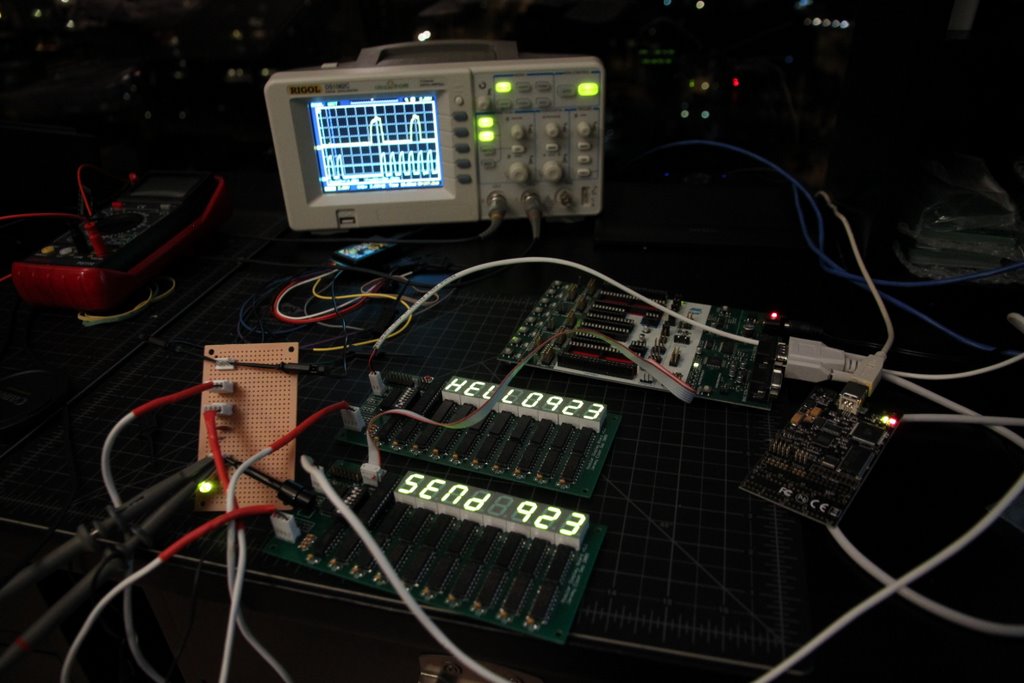 Fixed TWI Fixed TWISunday, March 14, 2010 -- jelson
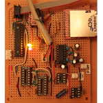
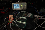
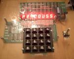
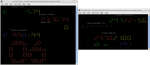
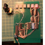
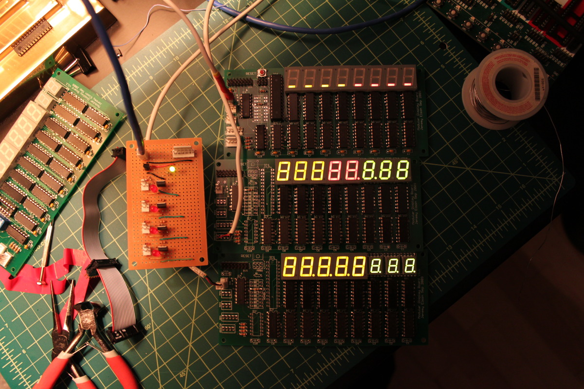
I have a pile of other plans, including getting the rocket to work. Which I did. The rocket works. I'm 99% certain if you go to the back yard and reprogram it, it'll work.Jon: Well, my friend, I'll take those odds, because you're right! Woohoo! I'm sitting in the R-ULAV right now. svn up, make, attach cables while making, and everything just works, right out of the repository.Jeremy: The photo shows the test rig I used to get the rocket to today's glorious state. Center: sender and receiver boards running twitest. Left: My new TWI bus board (v2!), with extra headers for test probes and even a power light. Back: the Rigol scope and USBee logic analyzer. Center: two programming boards.
bugs fixed Thursday, March 4, 2010 -- jonh
Tonight I got out to the rocket with the laptop and debugged a few problems.
I did use the "autotype" module to test disco mode, which was indeed pretty down and fun-kay. 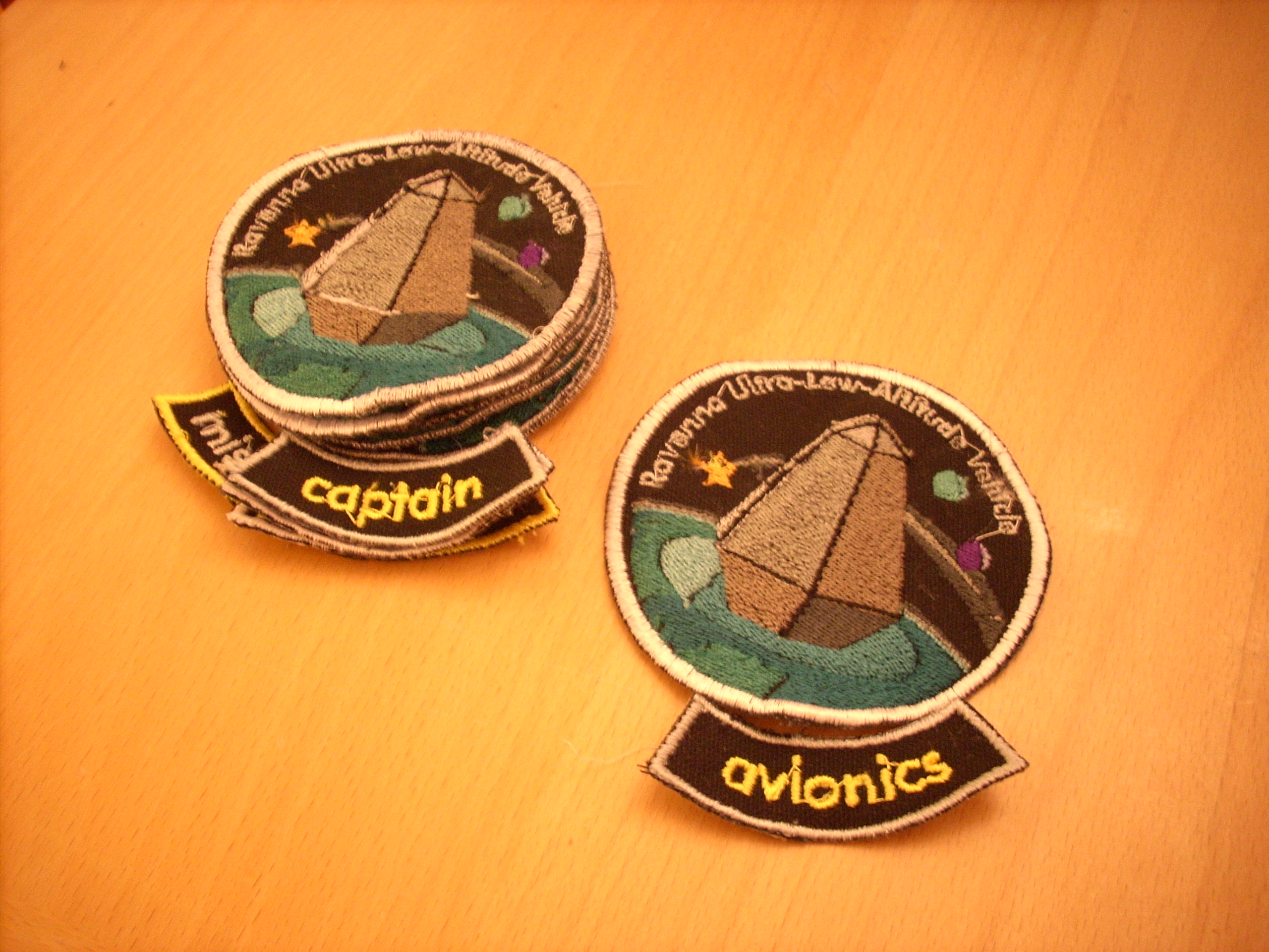 Patch embroidery; parts installed Patch embroidery; parts installedSunday, February 28, 2010 -- jonh
The flashlight cases are tied to the LEDs' cathodes, and mounting them tightly to the aluminum mounting blocks made good enough electrical contact to "ground" them to the rocket chassis. I use scare quotes because we don't actually deliberately ground the rocket. But anyway, why should it matter? Because the cathodes aren't actually at ground: the interior LEDs are wired common-anode, with a resistor between cathode and real ground. So the various lights were shunting random voltages to the chassis.
I clipped the zip ties, insulated the mounting blocks with electrical tape,
and zipped the lights back into place; all is better now.
So many loose ends tied up, let's keep going! I pulled the HPAM panel and soldered a new pigtail on the flaky thruster0 connector. (The old pigtail was made with 6" of Harbor Freight's 250-Foot Wire Storehouse, which I really cannot recommend; the insulation is way too thick for molex connectors. But if you insist, I'm sure you can find a 249½-Foot Wire Storehouse available on clearance at the Bellevue store.) Only one HPAM was actually connected to the Elson display board, and that with a way-too long cable; the other was hard-wired with a jumper. Jeremy had made me a replacement set of HPAM cables a couple weeks ago, but cautioned me to double-check the pinout. A good warning: they indeed didn't match the insalled cable. I poked out the molex pins and reordered them, and put the HPAM panel all back together. Unfortunately, the lights (which were hard-wired before) have stopped working, and when I plug the hobbs meter into its HPAM port, the CPU reboots. Drat! Well, by this time it's 10:30; enough for one day. 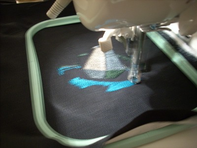 First patch embroidered First patch embroideredThursday, February 25, 2010 -- jonh
I did battle over breakfast with virtual machines, Windows XP, and a USB flash programmer even more obsolete than XP. Eventually, by a complicated process involving a chain of clunky software and two separate computers, I'm able to migrate designs from SophieSew to the writable embroidery card and transfer them to the machine.
It took about an hour of machine tending to sew. I think that was about half an hour of stitching, and another half hour of thread changes; the design has a ridiculous sixteen thread colors.
Keypad and TWI working in rocket Tuesday, February 23, 2010 -- jonh
I corrected a soldering error in the new keypad adaptor, and verified with Jeremy's standalone test program that the keypad is now working on its CPU. I installed the TWI standalone tests, and verified that TWI packets are successfully flowing in both directions across the rocket bus! I reflashed the rocket code into the CPUs, and unfortunately, not all is yet well.
CPU1 arrives Monday, February 22, 2010 -- jonh
Unfortunately, we didn't get very far. The keypad didn't work, which seems to be because the circuit board traces peeled off my little adaptor board. Eliot went to bed, then I made a new, sturdier adaptor and replaced the resistors on the TWI hub board. Hopefully we'll have some keypad and TWI joy soon!
Got TWI working! Sunday, February 21, 2010 -- jelson
I just checked in a big pile of code. I refactored the network stack so that network.c is strictly packet-oriented, and the framing code is separated (but not working) in a separate file called framing.c, used for underlying physical interfaces that are byte-oriented. I'm confident enough in this that I'm going to bring CPU1 in tomorrow so Jon can install it.  audio boxes audio boxesSaturday, February 20, 2010 -- jonh
audio simulator fixed Tuesday, February 16, 2010 -- jonh
In other exciting news, a KSEA (Seattle airport) air traffic controller has tentatively agreed to provide voice talent for the rocket, in the role of ... air traffic controller! Now I need to write a script for the part. 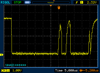 Getting TWI working Getting TWI workingTuesday, February 16, 2010 -- jelson
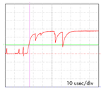
I started working through this, luckily with my trusty logic analyzer which has I2C bus decoding logic built-in. (This task would have been impossible without it.) There were a bunch of hard-to-track-down software bugs to work out, but the biggest problem turned out to be an electrical one. For bus sharing, TWI bus members are "open collector" -- that is, the bus needs pull-up resistors so that it is defined as being high if no one has seized the bus. Each TWI bus member can drive the bus low, but the only way to make it high is to disengage the drivers and let the pullup resistor bring the line high again. The issue was that the resistor had to be small enough that it could "charge" the bus back to Vcc in a timely manner. The definition of "timely" is a combination of the configured bit rate (i.e., how quickly the edge needs to reach its intended value) and the total bus capacitance (larger caps need more current to charge in that time). I arbitrarily picked a 10k resistor, since that's more or less the "usual" value of a pullup resistor, but things were acting very strangely. Out of desperation I searched the internet for advice on how to pick a TWI pullup resistor value, and found conflicting answers. One source said "I've seen values from 1k to 48k". Another said "4.7k is the standard value." Really, how much of a difference could it make to go to 4.7k to 10k? Out of desperation, I tried it anyway. Watching the logic analyzer's signals go by, things seemed to work for the first time! Then they stopped. Then they started again. I finally decided to get out my new analog scope -- the one we used to diagnose the problems on our other bus -- and there it was, clear as day (image above). This is a picture of the bus with 4.7k resistors. Wow. Those "square" waves aren't very square. It takes so long to charge the bus that the line isn't even getting all the way up to Vcc before it's time to discharge again for the next clock cycle -- it's about a volt shy. 10k resistors probably were, in fact, right on the edge: just a little bit slower, they charged the bus just a little less -- less than the detection threshold.
I fixed this in two ways. First, I changed the resistors to 2k resistors.
Second, I reduced the bus speed from 500KHz to 100Khz (which is the TWI
standard anyway). And now, voila!
We're reaching Vc and staying there for a while before it's time to discharge again. Now everything works -- here's the logic analyzer snooping on my first "hello" message from one CPU to another. 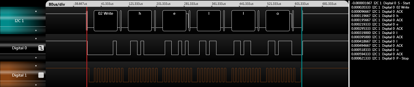
You can't quite see it at this scale but there's acking of each byte. The first block ("02 Write") means the master is saying "I want to send a message to node 2". The sliver after that is node 2 acking that it's ready to receive. Then, the master sends a series of bytes, each of which is individually acked by the receiver. Finally the master sends an end-of-message signal and releases the bus. Yay! I haven't pulled the TWI all the way through into the networking stack yet but, that's tomorrow's project.
EPB cured! Friday, February 12, 2010 -- jonh
There was still a two-foot section left leading to the HPAM panel, so I opened that panel up to cut its STROBE as well. When I did so, I noticed that the board had no power attached! Hmm; maybe that was causing a little trouble, too, drawing a good part of an amp through the EPB! Yikes. I spliced in a shielded strobe wire, plugged in a power lead, and put everything together. It works great! I haven't seet a flickery segment yet. Because we're still violating twelve of the Thirteen Rules Of Ribbon Cable, there's probably still lots of ugly on the wires; perhaps Jeremy will bring the scope back and we can re-check sometime. But it's working fine now, which is good enough for a treehouse. Even a rocket treehouse.  mounting audio, fixing joystick mounting audio, fixing joystickThursday, February 11, 2010 -- jonh
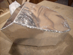
The speakers weren't too bad, either, considering the acoustic chamber
was a cardboard box.
embroidery fun Sunday, February 7, 2010 -- jonh
I tried to export my patch design from SophieSew, but it kept throwing an exception. I guessed that I had somehow created an object with a broken internal data structure, so I spent a delightful hour using divide-and-conquer, deleting some objects and testing to see if it would crash on export or not. Wow, I really am starting to loathe SophieSew; it makes a fun task tedious and crashy! (I don't actually loathe it; the author has done a great thing. But it desperately needs to be set loose into a community of open source hackers who will repair it.) I eventually got the file salvaged. Then I went through and tidied up the stitching order, and added some more design elements. Then I applied the Jeremy Elson principle: I shopped on alibaba for a bargain on an embroidery machine direct from Taiwan.
audio packaging Saturday, February 6, 2010 -- jonh
I pulled the joystick out of the rocket to mount it to the sidestick mount box, and discovered that in the process of laying out the sheet metal plans, I built the box inside out, so the joystick either doesn't fit into the elegant profile I built, or points the wrong direction. Dang dang dang! I'm hoping to correct the situation without rebuilding the box by pulling the joystick apart and turning the handle around. 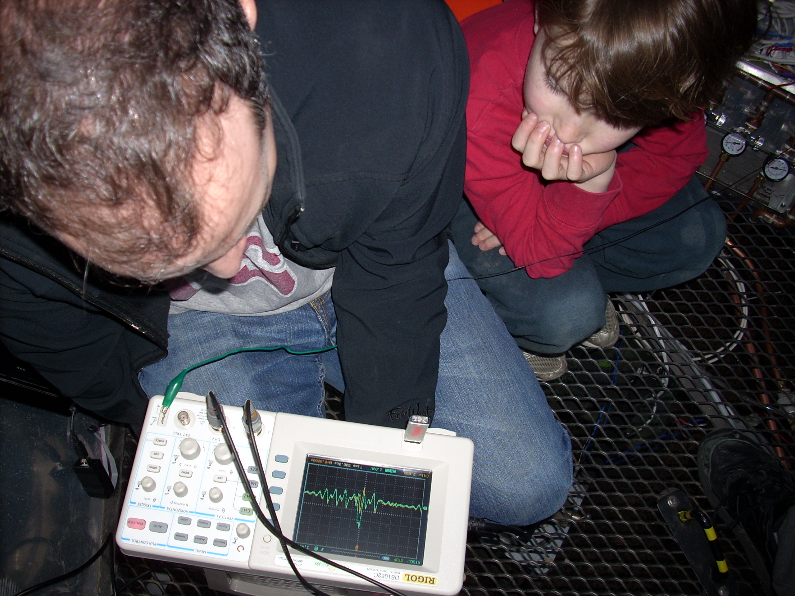 EPB on a real scope EPB on a real scopeSaturday, February 6, 2010 -- jelson
Yup, apparently violating all thirteen rules of capacitative and inductive coupling has resulted in a measurable amount of coupling. Notice also that even the valid signals are wandering -2V to +7.5V, on a system with only a 5V power supply. Jeremy snipped the strobe line in preparation for replacing with a shielded wire. He measured the effect again -- and we saw 2V of coupling just from the nine inches of ribbon cable leading out of the CPU0 board. But what really freaked Jeremy out was this: When he measured the strobe line on a board that wasn't plugged into the CPU, it was still coupled! The only coupling was through the power supply: the meteoric slew rate on the signal lines was enough to swing the power supply voltage almost a volt. Ouch. Our plan is to first install the shielded conductor for the strobe signal, which should reduce the wire-to-wire coupling back down to 2V, which while ridiculous, will probably get the rocket working again. If it doesn't, I'll rebuild the buffer board a third time with JD's proposed resistors to damp the slew rate to something finite, which should clean everything up quite a bit. Here's hoping!  patch digitization
Friday, February 5, 2010 -- jonh
On one hand, I'm terribly delighted that SophieSew exists: a free tool that lets you control embroidery machines, in contrast with the heinously expensive proprietary stuff from the machine manufacturers. On the other hand, the tool is orphaned and pretty buggy. The UI is mostly there to do tasks (spline manipulation, path operations) that other programs (inkscape) already do much more easily. It's modal, cumbersome and clumsy; just deleting objects is difficult, and undo is actually impossible. Setting the color of a stitch region is a seven click process, and you have to do each separate region one ... at ... a ... time. Aiieee. I finally got my design mostly done, and tried exporting it, and the export code crashes with a null-pointer exception! Oh man, is that frustrating, after hours of fiddling with the clunky UI. I suspect I'll be able to tediously copy and paste the parts out of the broken document and into a fresh document, using divide-and-conquer to take only a logarithmic number of steps, until I've eliminated the broken data structure. But what a humongous pain. I really hope the author chooses to open-source the app. The best outcome, I suspect, would be to rip out the file-format-export code (the "secret knowledge") and the code that fills regions with stitches, and use them to write a no-UI back-end to inkscape that consumes SVG and emits embroidery control files. I think Jeremy's coming over tomorrow with his new oscilloscope to debug the EPB problem. Yay! 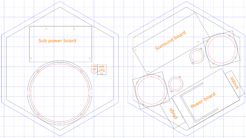 gutted speaker system
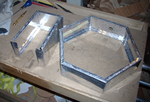
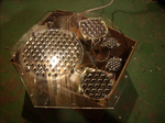
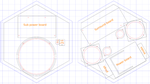
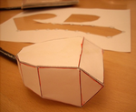
Wednesday, February 3, 2010 -- jonh
The good: I was able to inject 12VDC after the transformer and rectifier circuits and power both the subwoofer and main speaker amp boards. The ugly: there are three biggish circuit boards to make all this go. It's going to take a pretty big panel to mount it all. The weird: when I powered it off of a wall wart, it made a quite noticeable hum. This surprises me, since I'd assume that the supply current coming from the rectifier would also be noisy; I figured that the power regulator would be downstream of where I injected my noisy DC. (Although the giant heat-sunk thing I took for a regulator might have been the final-stage power transistor, now that I think about it.) This may be a non-issue since we're feeding the rocket fairly clean power, and perhaps not dirtying it up too much with our load -- only the 5VDC switcher would likely generate much junk on the 12VDC side. We'll see. The bad: the speakers had pretty substantial plastic housings, with obviously deliberately-designed acoustic ports. When I pulled that all out, the woofer wasn't quite so bass-y, and was a bit more rattle-y. I'm sure my aluminum-and-plexiglas mounting box won't be acoustically decent in any regard; hopefully it still sounds rumbly when it's all assembled. I traced out the parts, came back upstairs, and drew everything up in Inkscape. I wanted a cool hexagonal panel for this one, but it won't all fit in a single laser cutter panel! Here's a draft drawing with two hexagons. Maybe I'll do an irregular hexagon. 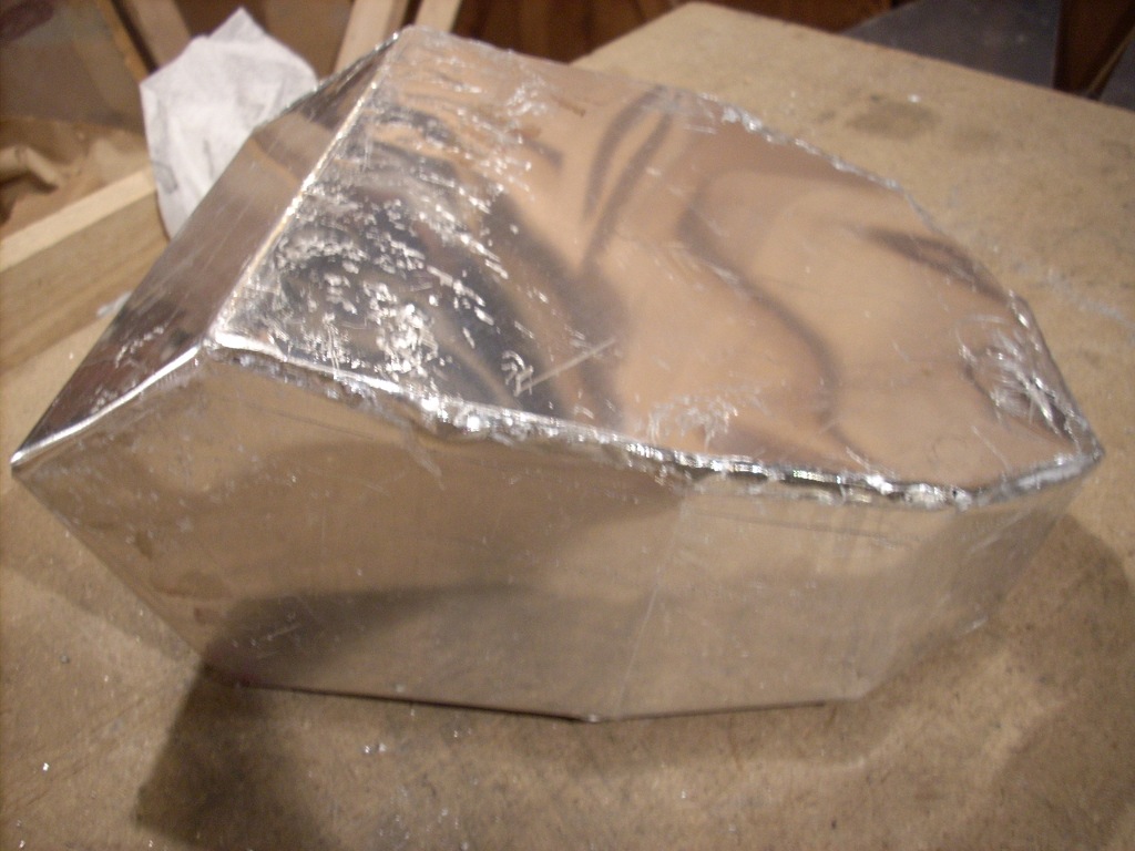 finished sidestick box
Tuesday, February 2, 2010 -- jonh
 box plans; EPB update
Monday, February 1, 2010 -- jonh
Over the weekend, Jeremy researched the EPB problem,
which we now think is crosstalk: the wiggling address and data lines are
probably coupling inductively to the STROBE line, generating spurious
signals that latch incorrect segments.
So, I'm trying to slog through 13 complex pages but they are basically summed up by this sentence: "The signal pickup problem makes direct logic drive with bundled multiwire cables almost hopeless."Jeremy and I grabbed JD today to sort things out. In classic JD form, he asked "you are alternating signal and ground on the ribbon cable, right?" Um, no. Jeremy went through all the ideas he got from H&H, and I also suggested the nuclear option: running TWI and breaking datagrams back out to EPB using a separate microcontroller at each remote panel installation. JD's recommendations were pretty accessible. Plan A, the easiest thing to try, is to string a separate, shielded wire for STROBE, isolating it to protect it from transients on the data channels. This involves only about five solder splices into the ribbon cable. If that doesn't work, we'll try Plan B: wire up a third variation on the EPB buffer board with resistors between the drivers and the long cable. The cable's capacitance together with the resistors should form a little RC circuit that limits the slew rate: how quickly the signal voltage ramps from ground up to 5V. Inductance is a function of that rate. Right now, the rate is "infinite". By tweaking resistors, we can slow things down to reduce the inductive effect, and then slow the software down to give the lines time to settle before we strobe them into the latch. I told Jeremy I'd run home and try Plan A right away, since it was so easy. He said no way! I must wait until he gets his new used eBay oscilloscope in the mail so we can look at the broken signals and see how things change with the new wiring. Obligingly, I worked on the sidestick box tonight instead.
'scoping the EPB Saturday, January 30, 2010 -- jonh
I played more with slowing down the EPB clock, and still no dice. It's surprising how consistent some of the display errors are: certain segments seem to like to light up together. Aaaarrgh.
software & scope Thursday, January 28, 2010 -- jonh
Unfortunately, the displays remain flickery and inconsistent, even though I tried adding NOP delays before the latch strobe. I really need to take a look at those lines with an oscilloscope. So I came inside and put together my SparkFun Jyetech scope kit.  EPB buffer EPB bufferMonday, January 25, 2010 -- jonh
And why do the symptoms change when I put my hand alongside the cable? Yikes: looks like the capacitance of the really-long Elson Parallel Bus cable has finally caught up with us. It was working fine the day before, but Sunday I rolled up the ribbon cable and stuffed it into the guide tube, a little closer to the huge conductive plane of the rocket's skin. It probably added just a bit more capacitance, enough to round off the signals' edges so the latches sometimes saw the wrong value. Now, flickery, slightly-incorrect displays add a certain amount of hard-core intergalactic realism, kind of like stained and marred aluminum skin. :v) But I think we'll fix this anyway; it should at least be working correctly before first launch. Jeremy suggests we can clear it up with a NOP (a "no-operation" instruction) that delays a little, giving the signal time to settle before telling the latches to accept it. I want to see the mucky signal on an oscilloscope first; I should assemble my new Sparkfun oscilloscope kit, take it out there, and check it out! This got me thinking again about the fact that I can't program the boards while they're plugged into the EPB. The first problem was that the USB programmer was trying to power the entire bus (seven amps worth of LEDs...), which I fixed by making pigtails that separate the 5V line, so the boards get rocket power, but data can flow from the programmer. Unfortunately, the pigtails weren't enough: The EPB reuses some of the programming pins, and the capacitance on the EPB was too high (even before Sunday's wire bundling) for the data rate used by the programmer. So tonight I made a new pigtail for bus 0: it has a copy of the 5V-separated programming header, and also an EPB interface with a 7407 driver (not shown in the picture -- Jeremy brought some in, but I left them on my desk) isolating the high-capacitance side of the bus from the CPU board and programming header. I sure hope it works this time! 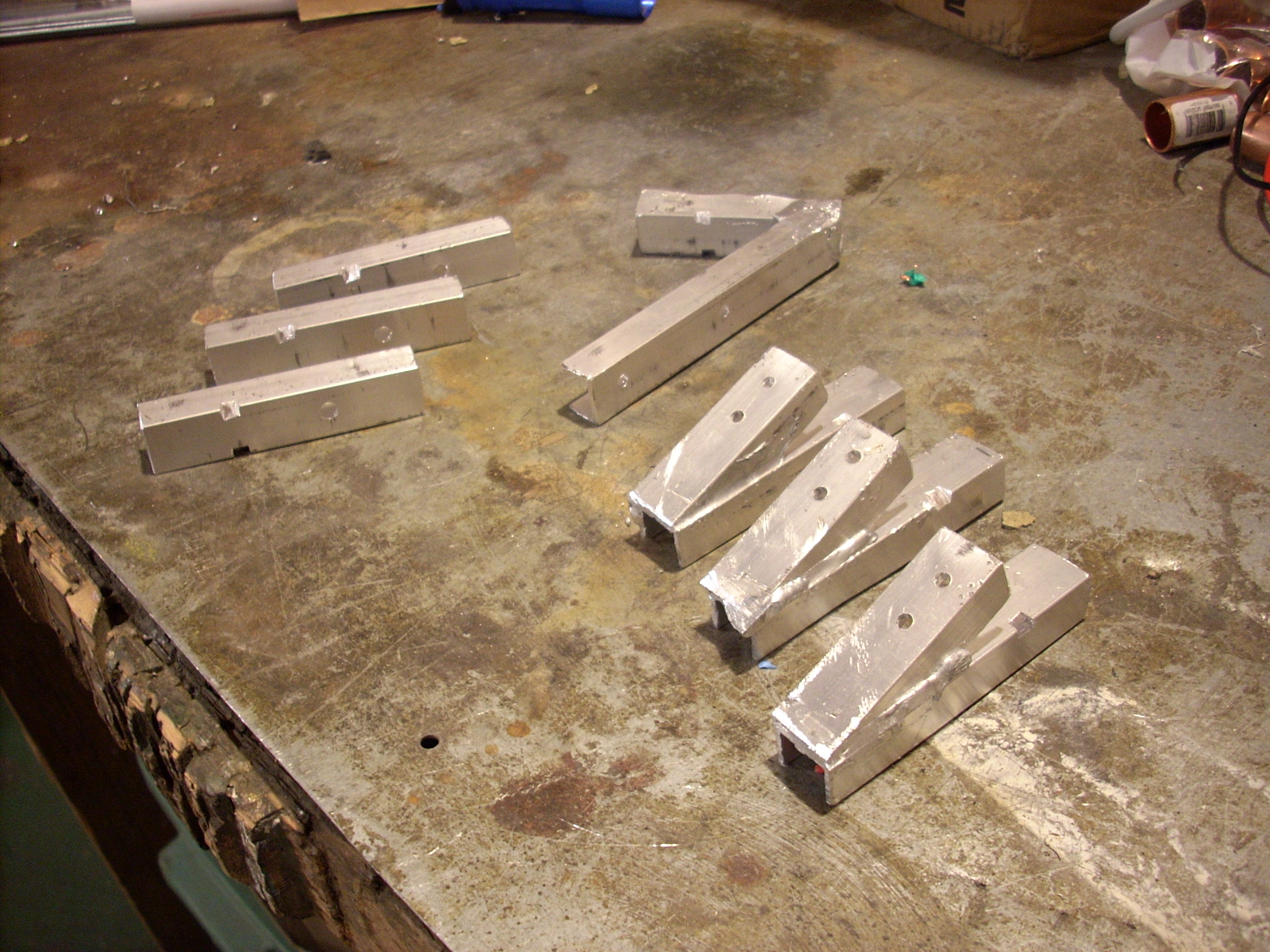 wiring & brackets wiring & bracketsSunday, January 24, 2010 -- jonh
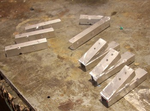
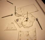
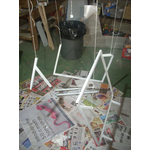
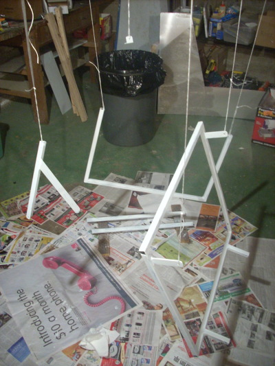
Finally, I made these aluminum mounting brackets for the exterior thruster lights, interior lights, and interior overhead light. I've had this pack of alumiweld rods sitting around in my shop forever, waiting for a chance to try them on something with no requirements of strength, reliability, or aesthetics. It's basically solder for aluminum: it has a lower melting point, and is supposed to bond to the base metal without melting it. I think I got it to work right, but I'm glad the only thing hanging on the brackets are flashlights. 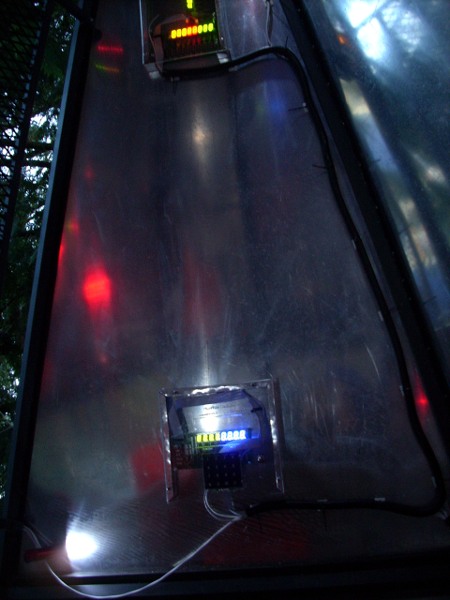 couch & wiring couch & wiringSaturday, January 23, 2010 -- jonh
Audio Thursday, January 21, 2010 -- jonh
Special effects Wednesday, January 20, 2010 -- jonh
The microcontroller boots up almost instantly, which of course will not do at all. I added a gratuitously slow bootup sequence modeled after the Bendix IFR GPS in Jeremy's Cardinal, the fanciest display in his panel, and hence the slowest to boot. After adding all this stuff, I realized I'd once again blown past our 2K RAM budget, so I spent a little while trimming memory, mostly convincing modules to time-share their offscreen bitmaps.  Some Systems Go!
Sunday, January 10, 2010 -- jonh
 Programming pigtails Programming pigtailsFriday, January 8, 2010 -- jonh
The solution: bring each CPU's programming header out on a ten inch pigtail. When not in use, they're tucked behind the panel; for servicing, we can pull them out and plug them in. Jeremy had an even grander vision: use the Atmel's self-programming facility, and make them programmable over the network, via the through-the-trench UART line. Yeah, I have to admit, being able to beam software updates to the spacecraft from the living room sofa would be pretty cool. I mean, it worked for the Mars rovers!  Adaptors AdaptorsThursday, January 7, 2010 -- jonh
 So much for rivets So much for rivetsWednesday, January 6, 2010 -- jonh
 The surprise The surpriseMonday, January 4, 2010 -- grandmajan
 Lots working! Lots working!Saturday, January 2, 2010 -- jonh
I finished up all of the mounting boxes,
and installed all but the one that's still missing its plexiglas panel.
Jeremy came over and did some finish work on the power panel and the HPAM
panel.
While I was mounting boxes, he completed wiring the water fill line.
Then he started routing display bus and power cables inside the rocket,
while I added flashing to the lid to reduce rain ingress.
I replaced some zinc hardware with stainless bolts,
and Jeremy wired up the joystick and the
HPAM-DA.
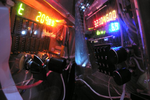
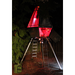
Although only two display panels and the power panel have enough wiring complete to function, the rocket has a beautiful red glow. As switches are thrown, lights show up one at a time, then twos and fours, then by the dozens. Push a switch on the panel; a blue light lights, a small click comes from across the yard, and water burbles into the thruster reservoir. Turn the master pneumatic valve; air hisses and the pressure gauges come alive. Press HPAM-DA channel 0 for the one completed thruster; a brilliant white jet of vapor blasts out and spreads out over the ground. It's pretty amazing. I can't wait to get the rest of the pieces wired into place! 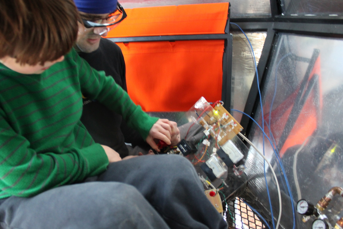 First electronics mounted First electronics mountedFriday, January 1, 2010 -- jonh
We tested out the power panel with the overhead light ... and the ammeter has already paid for itself: it read 3A, indicating that we'd plugged the overhead light into the 12V bus, when its resistor was configured for the 5V bus. Enough items on the power and HPAM panels needed tweaking that we took it back apart. Jeremy took some boards home to modify. I modified the power panel, adding connectors and rearranging a few incomplete circuits. I labeled all the circuits on the power panel to avoid a recurrence of the 12V/5V fiasco. I learned that Dymo label tape is heat sensitive, and that when shrinking heat-shrink tubing, it's really easy to set nearby tape to all ones.
Bending was getting slow tonight because my propane cylinder was almost empty; a trip to Home Depot yielded a new cylinder that heated things up much faster, including my left index finger. I laid out the remaining plexiglas panel (ready to laser-cut) and boxes (ready to construct in the shop). 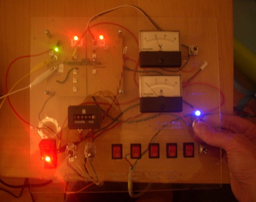 Wiring the power board Wiring the power boardWednesday, December 30, 2009 -- jonh
There are pigtails leading out to the HPAM boards and bringing HPAM-switched circuits back to the Hobbs hour meter and the lighting switches.  Installed couch, hull breach Installed couch, hull breachMonday, December 28, 2009 -- jonh
New site, couch upholstery Sunday, December 27, 2009 -- jonh
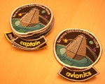
I took the opportunity to incorporate the fantastic mission logo designed for us by Noa Dvoskin. The plan is to render it as embroidered patches to celebrate the first successful mission. I also stitched together the fabric sling for the astronaut couch.  Flashlight fixtures Flashlight fixturesSaturday, December 19, 2009 -- jonh
More panels Friday, December 18, 2009 -- jonh
 All boards assembled
Thursday, December 17, 2009 -- jelson
Plexiglas panel Monday, December 14, 2009 -- jonh
The ribbon cable I have to test with precludes plugging in all four boards plus a keypad at the same time. I worked around this by creating an "Autotype" thread that just types in a given string at a given rate. It did have one funny little bug: the check for a zero terminator was incorrect, so it kept on typing out the rest of the .text section, eventually typing keypad 'D', which aborts the launch sequence.  OS bugs; flashlight mods OS bugs; flashlight modsSunday, December 13, 2009 -- jonh
I touched up the paint on the couch and ladder bracket.
I popped all the LED flashlights apart. I realized at one point that
part of my technique involved shearing a ring from the aluminum tube.
I tried to modify the technique to avoid that, but it turned out the
ring was distributing the force and protecting the circuit board;
two casualties resulted. I went back to the original technique,
disassembling and drilling grommet holes in all of the flashlights.
 OS debugging; painting parts; manifold chassis OS debugging; painting parts; manifold chassisSaturday, December 12, 2009 -- jonh
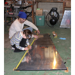
Eliot and I brushed a coat of black paint on the parts dangling from joists over the shop.
CPU upgrade Friday, December 11, 2009 -- jonh
 Final Power Board
Wednesday, December 9, 2009 -- jelson
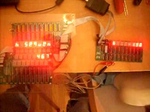
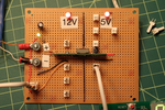
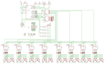
On the far left is the input section. We'll terminate the Romex cable coming through the conduit from Jon's house with a couple of ring terminals that will attach to the board with screws. The input is 12V; a green LED shows that house power is on. Lower left is a 3-pin terminal where we'll attach the master power switch. That will feed power to both of the output sections: 12V and 5V. The 12V output section is just the raw house power, switched but unregulated. It will feed the cockpit lights and the HPAM -- which, in turn, switches power to the thrusters and paint shaker. Power for the 5V output is generated by a switching power regulator and will be used for all the avionics panels. Both output sections have red LEDs showing they're active. Right now the 5V output section only has 5 connectors, but that's just because I ran out of connectors. There's room for 18. The photos on the right both show the new power board. The second photo shows the new board powering the mission clock panel and was taken with the lights off making the LEDs more clearly visible. Wow, those hundreths-of-a-second LEDs are ridiculously bright! Good thing we moved them from my office wall (where they're distracting) to the rocket (where they're just pure awesome).
 Primering parts Primering partsTuesday, December 8, 2009 -- jonh
PCB cables Monday, December 7, 2009 -- jonh
Sourcing parts Sunday, December 6, 2009 -- jonh
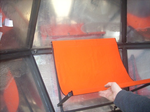
I picked up more LED flashlights. A trip to The Shack yielded a bunch of resistors to control them, plus some parts to build an audio amp. I grabbed a pair of bookshelf speakers and a pair of computer speakers from the thrift store, hoping to score an audio amplifier and maybe a speaker with enough bass to make a passable launch sound. Another Home Depot visit netted more bolts (for the couch and mounting the flashlights). At Joann's, I got a yard of safety-orange duck cloth for the seat. Tonight I tore apart the speakers. The bookshelf speakers are probably going to work for the bass, but something bigger would be nicer. The amplifier for the computer speakers was apparently in the subwoofer piece, which wasn't at the thrift store, so I'm still shopping. 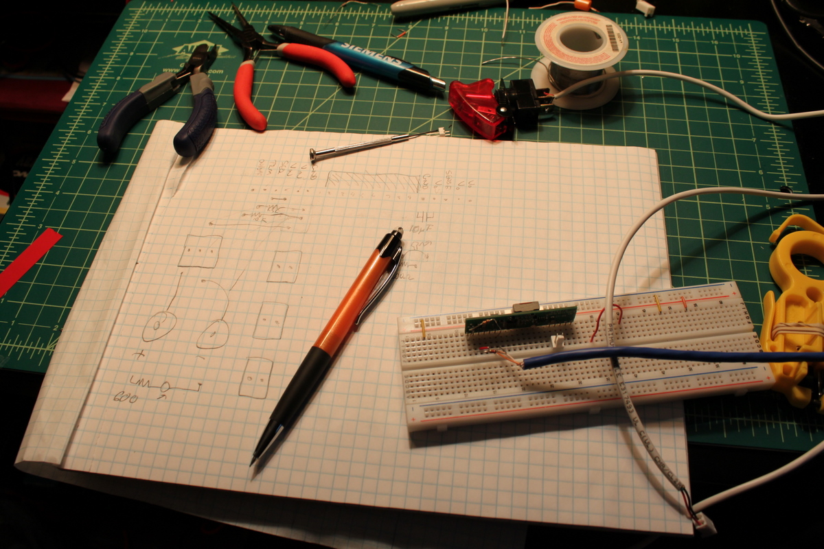 The Power Board
Sunday, December 6, 2009 -- jelson
Yesterday, I went to Jon's house to help him pull wires through the trench he'd built between the rocket and the basement. The trench will carry compressed air and water for the thrusters, power for the boards, and data between the house and the rocket. (The rocket has more utilities coming into it than my apartment!) We realized that the next step on the critical path was building a board that would distribute power from the house supply out to all the various panels. We'd planned on having such a board from the beginning -- I ordered the necessary components from Digi-Key 3 months ago -- but hadn't needed to put them together until today. I had a busy weekend, so only had an hour or so for board-building time. I thought for a while about the best way to construct the power board, drew a schematic, threw it out, drew a 2nd one, and then prototyped it on a breadboard. It'll have a big red power switch, two indicator LEDs, 12 5.5V outputs and 3 12V outputs, with room for future expansion. Some evening this week I'll build the real board. 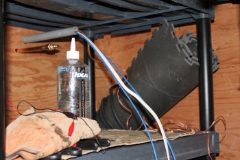 Pulling wire Pulling wireSaturday, December 5, 2009 -- jonh
Jeremy headed back home to build the power distribution board. I welded up the modified ladder over-center bracket and the metal frame for the astronaut couch. Fitting and cutting the frame's mounting brackets, drilling, welding, grinding, and wire-wheeling those parts pretty much soaked up the whole afternoon, especially with the 4:30 sunset. At dusk, I unwrapped one of the $1.50 Harbor Freight 9-LED flashlights and tried it out in the rocket. Wow, it's going to look great! 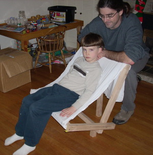 Prototype couch; ladder brace Prototype couch; ladder braceSunday, November 29, 2009 -- jonh
I proofed a version of the "astronaut couch" in wood and muslin, and cut the metal for it out of the few bars still littering the shop floor. It's mostly made of 3/4" square tube, and after I cut the pieces I needed for the couch, I had left a sliver less than 1/2" wide. Whew! The over-center brace that holds the interior ladder in place turns out to be rather wobbly from side to side. While I had the metal tools out, I cut a diagonal brace to fix it up. Eliot showed off the thruster for his grandma today. The water supply was pretty weak and intermittent. I realized that was because I had so carefully teed all the water supply lines into a single circuit, so the thruster was drawing air out of the other two thrusters. The fix is to do the simple thing I should have done in the first place: dip three separate water pickups into the tank.
Handles Saturday, November 28, 2009 -- jonh
Laying pipe Friday, November 27, 2009 -- jonh
One cool feature is that the water line has an air hookup: when freezing temperatures are forecast, I can close the water valve, plug the compressor into the side, and blast the water out of the buried water line through the reservoir. We tested this out, and it worked great. JD taught me how to feed the pulling line through the conduit: tie it to a little bit of plastic bag, and suck it through with a shop-vac. That worked pretty well. Unfortunately, we weren't able to pull the 14ga power wire back through the conduit's seven (yikes!) 90-degree bends. Hopefully it'll go better on another try, with two adults working at it. We filled the trench back in and got our yard back. I hope the conduit doesn't put up too much more of a fight! 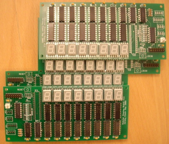 Trenching; building boards Trenching; building boardsSunday, November 22, 2009 -- jonh
For those of you keeping track, the trench has become a Multi-Purpose Service Infrastructure Component. Here's what we're burying in it:
 Building boards Building boardsSaturday, November 21, 2009 -- jonh
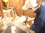
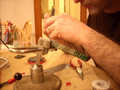
In the photo, you can see that I'm using a rubber-jawed soldering vise. Andy, a good friend that taught me all about electronics and computers and math and pretty much everything else, loaned that to me when I was little. Andy passed away recently. Every time I solder a project with it, it's bittersweet.
Reaction mass reservoir Friday, November 13, 2009 -- jonh
Audio software Thursday, November 12, 2009 -- jonh
In any case, I used Audacity to make some rumbly rocket booster noises. I also mixed together some clangs from the web to make a docking noise, and sliced up the classic Pong beeps and boops. I wrote up the code in the simulator that will drive the audio board, and the sound stuff all works in simulation now. I still need to plumb the hardware side through (SPI to the flash chip that will hold the sample buffer, writes to the DAC that drive the amplifier, and the TWI that carries network messages among boards) and make sure it sounds good. 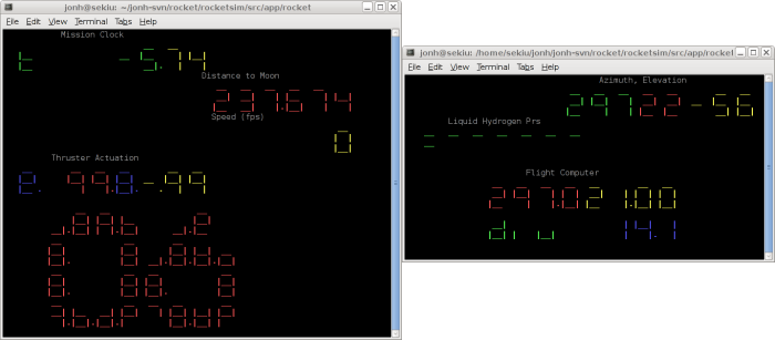 Distributed systems software Distributed systems softwareMonday, November 9, 2009 -- jonh
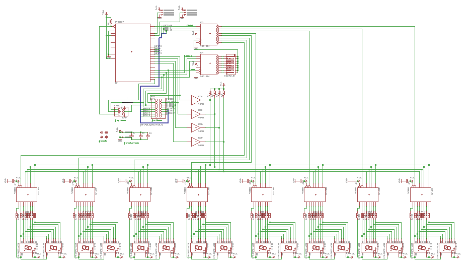
That had a few fun components. First, somewhere along the line, the rocket became a distributed system. The Elson Avionics bus supports eight 8-digit displays per processor, and on panel design day, we ended up with a total of twelve displays. Furthermore, there will be an audio board, with its own microcontroller, to add some environmental acoustics. These three controllers will be interconnected by the "three-wire interface" (TWI), one of three bus standards implemented on the Atmega microcontroller. (TWI is a multi-master bus; SPI is a single-master bus, and UART is a point-to-point standard.) So I implemented a TWI module in the simulator, wrote the rocket networking stack against the simulator, and wrote a bunch of modules that ship keystrokes and thruster status messages around. My first cut at the networking stack was a clumsy state machine. Jeremy, drawing on his extensive background writing little tiny network stacks, pointed out the world of software maintenance pain that I'd opened up. I started experiencing that pain within 48 hours of the first implementation, so I rewrote the stack using his recommended architecture. Then I organized the remaining modules and filled out the remaining display functions. Mostly, this meant dragging modules from their rough prototypes to completed, integrated components. For example, when the "Launch" function is selected, it draws a giant countdown on the bitmapped display, updates the Mission Clock, and advances the speed and lunar distance displays. I still need to implement and test the TWI stuff on real hardware, but this is all pretty satisfying: Once we build, mount, and wire the hardware, we can turn it on and start firing the thrusters with the real software.
Plumbing tests Wednesday, November 4, 2009 -- jonh
I tried to mount the over-center lock, and that didn't go so well. For reasons I don't understand, the screws bound up in the tapped holes. One, when I tried to back it out, even broke off in the hole! Bummer.
Pressure manifold Monday, November 2, 2009 -- jonh
 Plumbing PlumbingSunday, November 1, 2009 -- jonh
I tapped the mounts for the over-center lock, test fit it, trimmed off the extra metal (from yesterday's fiascos), cleaned it up, and primered it. I tapped the mounts for the lid cable tabs, and primered them. That tied up a bunch of loose ends, and left me ready to start in on one of the remaining big steps... Primary pneumatic power. The rocket uses pneumatic power for primary boost and orbit-adjustment rockets. Specifically, I'll be running a pipe from an air compressor ($90 on sale) in the shop. In the rocket, it will provide opportunities for valves, pressure gauges, and leaky-gas noises. And also, it'll power a paint shaker (also $90) bolted below the chassis, for shuddering takeoffs. (We're planning to add some suitable higher-frequency takeoff noise to go with it, in the electronics subsystem.)
Then, once in orbit, orientation and smaller adjustment burns will
be provided by blasting jets ($8 each)
of dihydrogen monoxide reaction mass. (This was a component I thought for sure
would require custom machining, but no, Harbor Freight wins again.
Early playing with these, showed that the RC delay in a 15' air hose
is so great that the vapor sort of hisses slowly to a start and again to stop.
To get a satisfyingly sharp retro "blast", I had proposed to connect
a joystick mechanically, through bike cables, to actuate the thrusters.
Along the way, Jeremy convinced me that it was much better to actuate
them electrically; he found solenoids on eBay for $15 apiece.
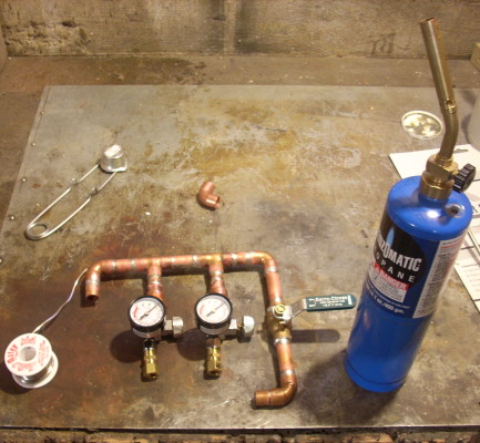
So, today, I launched into the pneumatic plumbing. I bolted all three thrusters into place, and bolted the booster (paint shaker) hangar into place. Each thruster received its series of 1/4" NPT fittings: an elbow, a male-male coupler, a solenoid valve, and a 3/8" compression-fitting coupler. That takes the output end of the plumbing as far as I can; I'm still waiting for a fourth solenoid valve to return from Jeremy's avionics shop. Next, I started on the distribution manifold. It begins as a 1/2" sweat-fit copper pipe, passes through the propellant master valve, and splits through a manifold to three female 1/4" NPT fittings. Each fitting feeds a regulator and pressure gauge, and terminates in a 3/8" compression fitting. The third output is not yet soldered in place, because I need to pick up a third regulator. I have to have the whole stack of NPT fittings together to be sure that, once soldered, the stack gets tight just as the gauge is facing up. So, I'm already most of the way through the plumbing! I'll need to add a supply pipe plus a half-dozen runs of soft 3/8" tube between the compression fittings. I confess that an important benefit of getting the plumbing so far today is that it will make Jeremy itchy anxious to start clicking those soleniods.
Lid installed; ladder lock Saturday, October 31, 2009 -- jonh
I installed the finished lid on the rocket, cotter-pinning the hinges, and made tabs for the lid-limit cable. Then I built the over-center lock for the inside ladder. That took three tries (measure thrice, cut thrice, I always say): On the first try, the linkage tried to fold itself outside the aluminum panel. I adjusted the lengths, and on the second try, it tried to fold itself the other way, through the ladder pole. The third time was a charm; it's now ready to tap, paint, and bolt into place.  Riveting the lid Riveting the lidFriday, October 30, 2009 -- jonh
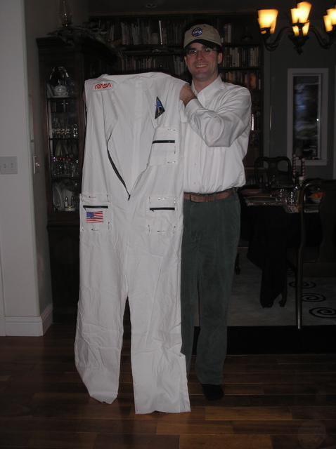
 Flight suit finished! Flight suit finished!Thursday, October 29, 2009 -- grandmajan
 Handles, plumbing procurement Handles, plumbing procurementTuesday, October 27, 2009 -- jonh
I parted with $100 (what we're coming to call a "rocket nickel") at Morgan's Plumbing, Home Depot, and Lowe's, collecting all the goofy little fittings I need to transition between 1/4" NPT air fittings, 1/2" sweated pipe (cheap!), and 3/8" compression fittings (adjustable). Strangely, one specific fitting was out of stock at all three stores. I hope no-one else is building an identical rocket just down the street. 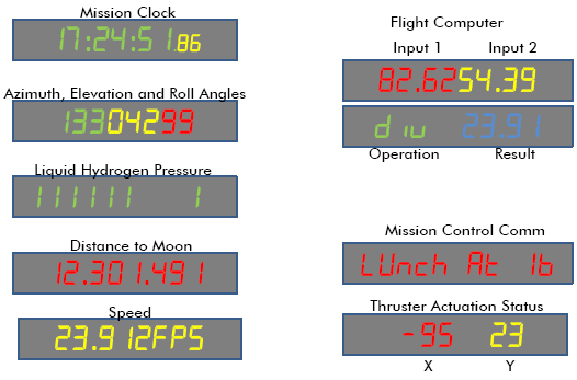 Planning the final panel
Monday, October 26, 2009 -- jelson
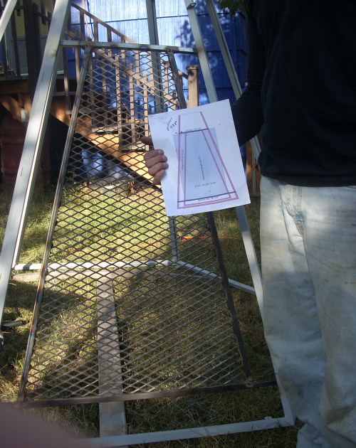
I used PowerPoint to draw a dozen different proposed panel modules. Then, one evening after work, Jon and I clambered into the newly risen rocket with a dozen correct-scale printouts of a rocket panel. We cut each module out and pasted the ones we liked all around us. I have to say, seeing all those displays up in the rocket, even though they were just paper, was pretty exciting.
Tonight, I started the process of building all the final boards --
labelling each one with its intended function, and taping all the
right colors and sizes of LEDs into it. It feels like we're almost there!
 Handholds and latches Handholds and latchesMonday, October 26, 2009 -- jonh
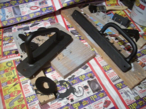
After Eliot was in bed, I went down to the shop and cut up some steel to make handholds and latches. I love making the beefy handholds from 1/2" steel rod, because step 2 is clamping rod into a vise and beating the baloney out of it with a sledge hammer. If it ends up the wrong shape, you clamp it differently and then beat the baloney out of it with the sledge hammer. It's nice when you run across problems so simple that you can fix them with a sledge hammer.  Dress rehearsal Dress rehearsalSunday, October 25, 2009 -- grandmajan
So: Next step: get the zipper installed. Find the zipper in the big bag of stuff. No zipper. A huge bag of anything I "might" get to, and the next step item was missing. So off to Jo-Ann's, 10 mile round trip, to get another zipper (actually got two varieties just in case...) Got home and the girls were up from their nap. Whee! So we happily had kid/grandparent playtime, read Box Car Children with Eliot, ate pizza, more fun playtime, then kiddo's bedtime. Ah, time and energy gone, so it was time to go home, dragging the suit home in just about the exact same state I had taken it over in. Which was OK, because I would much rather play with the kids. :v) Sewing I can do at home. So today I pinned, then basted in the zipper. Several pin pricks later I was ready to sew the thing in. Wow! Installed in the first attempt. Yeah! While sewing I was contemplating what to do about the tricky design of the collar, and began wondering - is this thing going to be a scratchy, bothersome thing that he might not like anyway? So we await the verdict on that from the rocket manufacturer and the astronaut who will have to live in it for awhile. 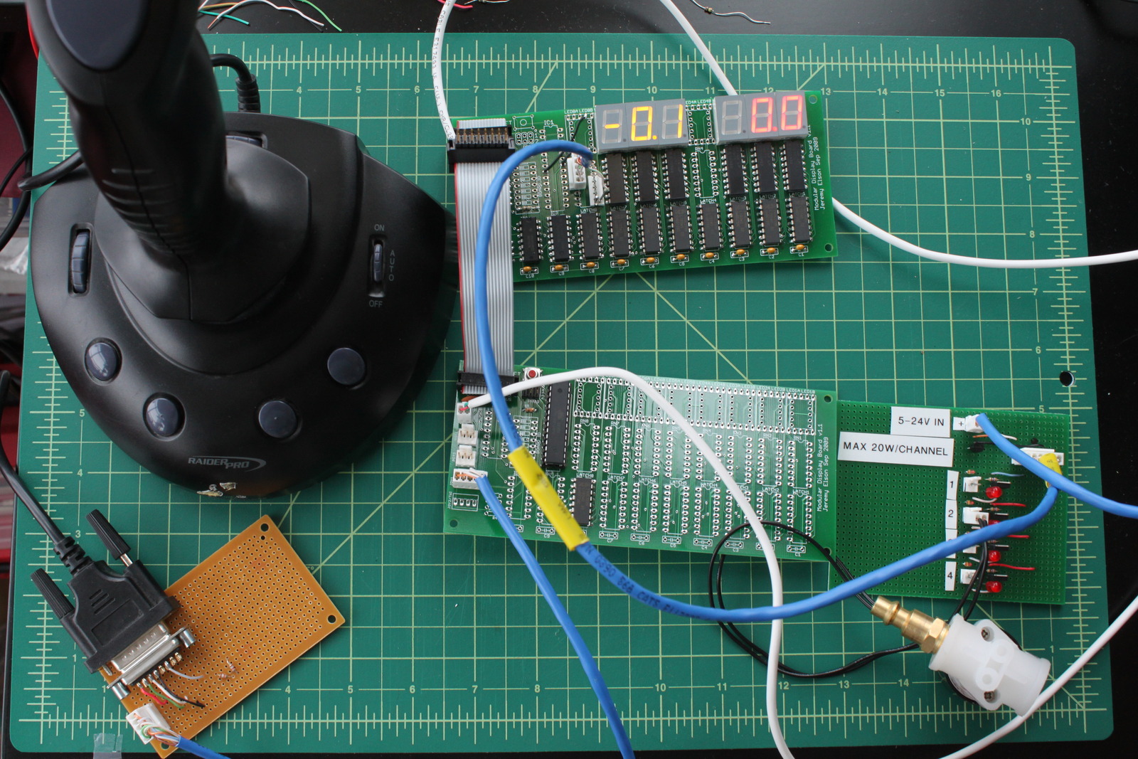 Joysticks controlling thrusters -- it works!
Sunday, October 25, 2009 -- jelson
I don't think I really appreciated how complex this project had become until I sat down yesterday to make this all work. I was shocked to discover that there are no less than 6 separate components that must be chained together in a long line:
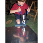
The past two days were mostly spent building all the special cables to connect the components to each other and writing software. ADC-read voltage values from the joystick are converted into positions assuming the hyperbolic resistance-to-voltage curve shown in the joystick entry. I settled on 40k resistors. The positions are scaled to a value from -99 to +99, with 0 at center. Hysteresis is used to threshold the joystick positions; +/-50 triggers, and +/- 30 releases. Depending on the joystick direction, one of the three thrusters is fired. It all works! Here's a video showing the whole system:
Lid panels Sunday, October 25, 2009 -- jonh
Ladder foundation; paint Saturday, October 24, 2009 -- jonh
Parts painting Thursday, October 22, 2009 -- jonh
Rope ladder assembly Monday, October 19, 2009 -- jonh
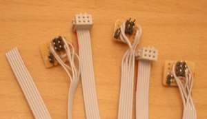
Monday, October 19, 2009 -- jelson
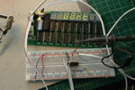
Of course, having written a time-sync dissertation, this clock would need to be accurate. My original plan was to signal the start of each second using a single GPIO line, but Jon convinced me to use a full-fledged serial port to send complete time messages. After some resistance (I was afraid the serial port would be too complex) I agreed. The first step was to establish a data link between my PC and the board. I bought some MAX-232's, which are chips that convert the voltage used by a PC serial port to the voltage used by typical microcontroller. I prototyped an interface board that would take a PC serial port, short-circuit the flow control lines like a null-modem does, and put the 2 data lines into the MAX-232. I wrote code on the controller to configure the UART, accept serial port interrupts, timestamp them with high precision, and enqueue the characters. As a first test, I wrote a simple program that would just read characters and display them. It was surprisingly cool: I could type on my PC keyboard, and see messages scroll across the 7-segment LEDs! Next, using my newfound power to get messages from the PC to the board, I set out to get my clock to tick correctly. I wrote a small program that runs on the PC which sends a message to the serial port once every minute, precisely at the beginning of the minute, telling the board what time it is. (The PC's clock is synchronized using NTP, via the Internet.) The clock board lets the clock run free in between the messages; when it gets one, it both sets the time and trains its oscillator so that the length of coming free-running minute will be accurate. It annoys me that most time-sync software doesn't do this; usually, they just jump the clock to the right value every few minutes, giving you a clock with a sawtooth pattern. Finally, I built a permanent pair of small connector boards so I'd be able to feed both power and serial data into a single 4-conductor cable to run from my office PC to the clock. If this sounds like a project that consists mostly of a hundred tiny little details, you're right. But the result is awesome, and I'd estimate remains accurate to within 20ms of the PC's clock throughout the entire minute between pulses:
It's now hanging on the wall outside my office. If you're ever at Microsoft, stop by 99/2374 and take a look at it!
 Assembly! Assembly!Sunday, October 18, 2009 -- jonh
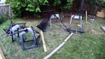
We settled on the latter plan. The three of us had no problem righting the legs-and-hips section, and then trotting it across the yard to the concrete footings. We bolted the legs to the footings, and within moments Alex and Eliot had clambered into the rocket, seven and a half feet high. Jeremy and I inverted the torso section, and held its open edge up to a matching edge of the hip section. Alex and Eliot turned a couple straps into an ersatz hinge. Jeremy ran a strap from the inverted top of the torso up to Alex. Jeremy and I swung the torso halfway up, so that it was lying sideways, then Alex pulled his strap to right it the rest of the way. We hacked a few cedar sprigs out of the way, and bolted on the torso.
Wow! It stands up nice and high, and sure looks like a rocket.
What a cool treehouse. Today's a big day.
More panels Saturday, October 17, 2009 -- jonh
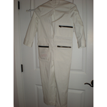
 Flight suit Flight suitFriday, October 16, 2009 -- grandmajan
Now to get this thing finished before Eliot has grown out of it or lost interest. How long do you think it will stay white? Oh, who really cares! :v) After two fittings, here's what we have so far. Once we know it fits I will be putting in the hefty black metal zipper up the front, then a black thick cowling-like collar (to keep the helmet "air tight" - ha, like a fuzzy space helmet will need that. But, you know, it's the look we're after here.)
 More panel riveting More panel rivetingThursday, October 15, 2009 -- jonh
More riveting with Eliot Saturday, October 10, 2009 -- jonh
Saturday, October 10, 2009 -- jelson
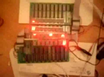
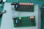
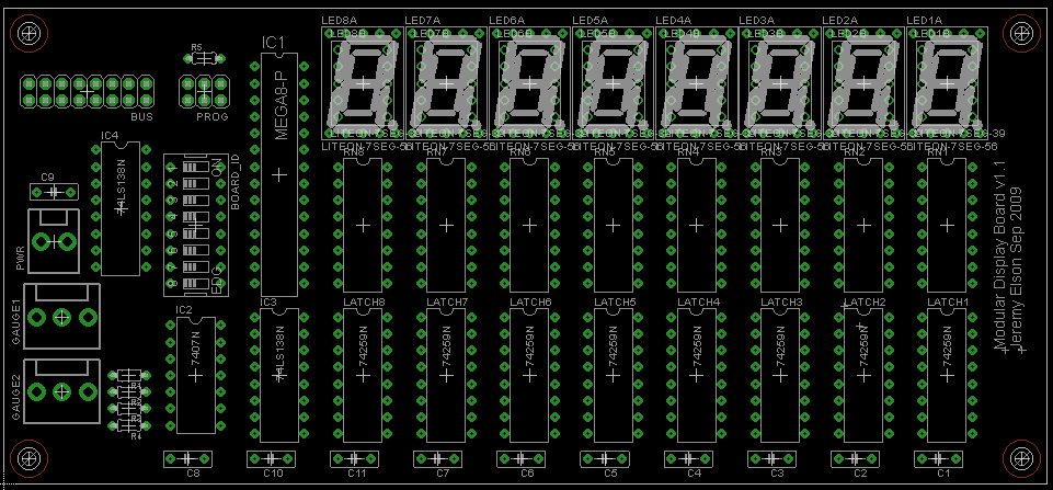
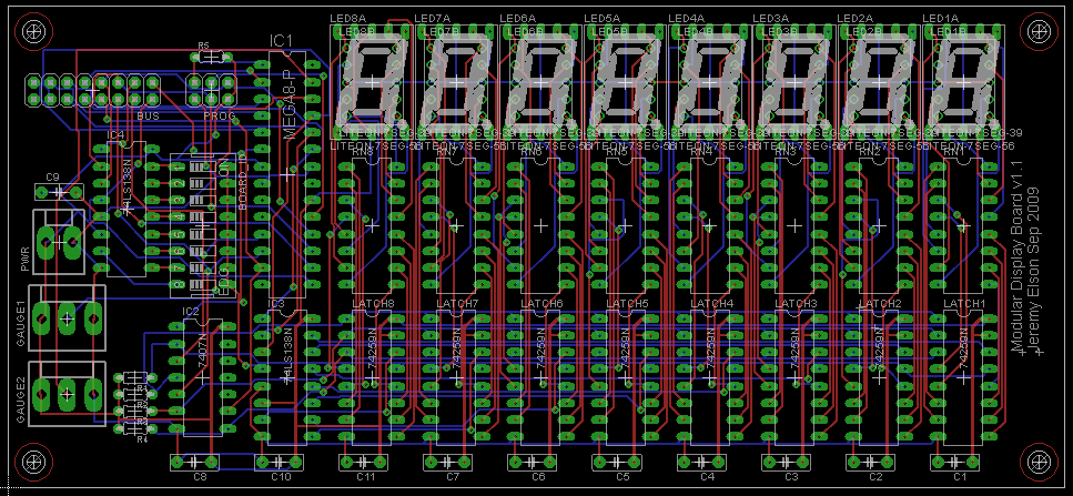
The v1.1 boards were more evolutionary than anything else, as you might know if you've read the rest of the entries in painstaking detail. Perhaps the most visible change is that it now supports larger LEDs (0.56", vs the original that only supported 0.39"). Through some clever routing, a single board can take either size of LED, or a combination. v1.1 also have some convenience features: mounting holes, a reset button, more analog-to-digital converter pins now available, a joystick port (a single header with 2 ADC inputs, plus a GPIO input for the trigger button), and so forth. To the right is a picture I took of the first v1.1 board with LEDs soldered in, showing that both the larger (green) and smaller (orange) LEDs work together. This v1.1 board doesn't have a processor yet; it's being controlled via the data bus by one of the older v1.0 boards. I also have a glamour shot of my "signature" on the new PCBs. By v1.1 I'd figured out how to add custom silkscreening so I put my name on it.
 Reading a joystick
Thursday, October 8, 2009 -- jelson
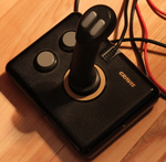
After some research, we discovered that old-style PC joysticks are actually just two potentiometers, one for the vertical and horizontal directions. Joystick buttons are just plain old pushbuttons that ground their inputs. This should make it easy to attach a joystick to a microcontroller. In theory. Step one was finding a joystick. Modern joysticks are digital monstrosities with USB interfaces. We needed a 1990's era joystick, and they were surprisingly hard to find. No one uses them any more. Finally, one popped up on Craigslist for $1 nearby in Redmond, so I biked over there after work one afternoon a couple of weeks ago and picked it up. The 5-year-old previous owner was excited to hear his old toy was going into a rocket ship. I promised him a ride once it was finished!
Wait, what am I talking about? Random stray circuit boards scattered around the rocket will just make it better!
HPAM test, riveting, and software Monday, October 5, 2009 -- jonh
Jeremy showed up about 10:20 to test his High Power Auxiliary Module, the hand-built protoboard that takes signal-level outputs from the microcontroller board and switches transistors to drive higher current devices, like the solenoids. We tested the paint shaker (video), and got some satisfying blasts out of the thruster jets. Then I ruined one of the jets trying to "improve it" in the shop. After Jeremy headed out, Eliot and I riveted two panels onto the lower frame. Sunday, October 4, 2009 -- jelson
Today's main project was building a small board that would let the main rocket panel actuate the rocket's "engine" and "thrusters". As Jon briefly describes in his todo list, he's going to run compressed air to the rocket from his garage air compressor. This will power both the rocket's "engines" (actually a paint shaker that will vibrate the rocket for "takeoff"!) and its "maneuvering thrusters" (actually pneumatic engine cleaning guns). Jon's original plan was to rig up some kind of mechanical valve to let the pilot turn these systems on and off from the cockpit, but I convinced him to buy some $18 solenoid air valves I found on EBay. That gives us the flexibility to have the thrusters controlled both from software and manually by the pilot We're going to write some sort of "launch sequence" program that will fire up the engines and thrusters; once in orbit, the pilot will be able actuate the thrusters using a joystick. Jon was resistant to the idea at first, but as soon as the valves arrived and he saw one turn on his paint shaker, he was glad the rocket's electrical and pneumatic systems would be working as a team!
Since we only needed one or two of these boards, I just made them by
hand rather than getting PCBs professionally manufactured. And,
to really give the thing that 50's Fictional Space Program feel,
we gave the board a ridiculous name: the High Power Auxiliary
Module.
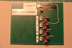
The end result, I must say, is super cool. Here's a video clip of
Liesl playing with the button box. Each button press lights up an
LED. I also attached a test solenoid to Channel 3; if you turn up the
sound you can hear it clicking when she pushes Button 3.
I'm heading to Jon's place tomorrow to try it with a solenoid that has
real air running through it .... how exciting!
Aluminum panels, booster bracket Saturday, October 3, 2009 -- jonh
I also sanded the last aluminum leg, so I'm ready to bolt all three to the gantry and dig the concrete pads into place in the back yard. Three more hours went to making the main booster bracket. I computed the final dimensions, cut the steel, drilled holes for bolts that attach to the paint shaker and to the tabs on the gantry, and welded it to shape. It still needs to be ground and painted, but it's far enough now that I can bolt it onto the rocket to try it out (whee!) and measure for the pneumatic plumbing.
Prototype PCB Friday, October 2, 2009 -- jonh
Thursday, September 24, 2009 -- jelson
I also added a reset button, some nice silkscreened labels on everything, and more generous clearance between pads and vias to make the boards easier to solder without accidentally shorting two nets. Ever the eternal optimist, I ordered 20 of these boards -- enough for two full stacks, plus a couple of extra for development, or just hanging on my office wall. Why not, they're less than $3 each (plus $90 setup fee and shipping). They should be here October 5 -- something to look forward to after the NSDI deadline has passed!
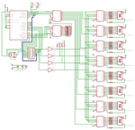
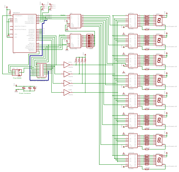
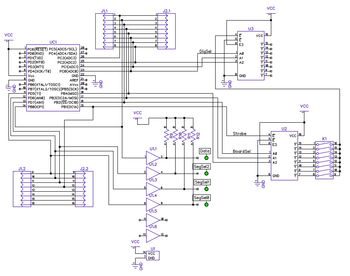
Here's the final schematic and board layout. Note the schematic
is much cleaner once I learned how to attach remote nets just by
giving them the same name; the ugly and not-very-informative
blue bus no longer snakes its way through the center. Plus,
the bus connector's pins are all assigned to a logical name,
rather than a microcontroller pin: exactly how it should be,
since from revision to revision, we want the mapping of the
logical function (e.g., segment select) to position on the bus header
to
remain consistent, but we don't really care which microcontroller pin
is being used to drive the bus.
Wednesday, September 23, 2009 -- jelson
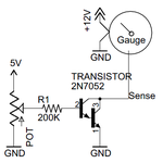
I have been spending most of my days lately writing a paper for a work deadline coming up, but my thoughts occasionally drifted back to the problem of driving a gauge. A few minutes searching both Digi-Key and Google revealed that, for some reason, high-current digital pots just don't exist. No one makes them. People on the Internet ask where to find them and they're answered with "They don't exist." I don't understand why. I started to think about taking a different approach. Really, why does the gauge want to see variable resistance? Presumably because it's measuring the resultant current. So, what if I found some other way to vary the current, other than varying the resistance? Transistors are current amplifiers ... might I use one? People often use transistors as simple switches, because there is such high gain between what you put in the control pin (the "base current") and what flows through the high-current pin (the "collector current"). Put in any reasonable base current, and the collector current gets driven up to the transistor's maximum. This is called "saturating" the transistor. But there's a range of base currents, before saturation, for which small increases in base current give proportional increases in the collector current. I wondered -- could I try using a transistor in this way? Yesterday, I measured the maximum current draw required by the gauge at 250ma for full deflection. (0 current gives 0 deflection.) It so happens I have some Darlington transistors here that have a current gain ("Hfe") of 20,000. So if I want 250ma of collector current, I'd need 250ma/20,000 = 12.5 microamps of base current. So I need a resistor on the base that gives me 12.5 micromps. Assume base voltage is 5v, transistor's forward voltage drop is 2v. That leaves 3 volts visible to the resistor. 3v / 12.5ua = 240Kohms. I attached a 200k ohm resistor to the base of my transistor, and sure enough, my gauge's needle went to full deflection and drew about 250ma.
Sep 21st's entry showed a gauge moving when I had a mechnical pot attached, too. But there's an exciting difference here. Today's pot is only passing 12 microamps, not 250ma as before. In fact, I attached an ammeter in series with the pot, and it couldn't even measure the current flowing through it (its resolution was 1 milliamp). A dozen microamps is so small that I should be able to pass it through my digital pot, which is rated up to 1 milliamp, without melting it. I'll try attaching that tomorrow and see if it works! This is so exciting: another tool in my toolbox!
Monday, September 21, 2009 -- jelson
It's not too hard to find cheap used car gauges on Ebay. A couple of months ago, I paid all of $0.99 (shipping included!) for really cool-looking electroluminescent oil temperature and RPM gauges. We thought they'd be perfect for the rocket's control panel. Unfortunately, we couldn't figure out how to get them to do anything. They'd power up when attached to a 12V supply, but we couldn't figure out what kind of signal to put on the sense line to get the needle to move. I learned that car part manufacturers don't document their interfaces as meticulously as most other electronics components. If you go onto Digi-Key and buy so much as a 7 cent LED, it'll come with 8 pages of documentation, exhaustively describing its electrical and mechanical properties. Car gauges seem to come with nothing more than a flyer that says "Put 'er in your car! Then go get a cigarette! Yee haw!" After hours of web research I found a catalog page for a 3rd party fuel-tank sensor that said "Attaches to standard gauge (60 ohm full - 600 ohm empty)." At last, some data! Apparently you vary the resistance on that signal wire. I tried attaching our fancy gauges to a pot with the proper range but the needle still didn't budge. Finally, I speculated that perhaps the gauges were broken and that's why they cost $0.99. Jon took me on my first trip to a junkyard, charmingly named Pull-a-Part, and I paintakingly extricated a couple of gauges out of the dash of an Oldsmobile (I think). Hooked that up to a mechanical pot, and when I adjusted it with a screwdriver, the needle moved. Hooray! It's too bad those gauges are so ugly. The broken EL gauges looked rocket-y; the ones that work just scream "80s sedan". That brings us to today. How do you get a microcontroller to provide variable resistance? I discovered a clever device called a digital pot that does exactly that: every time you strobe one of its pins, it increases (or decreases, your choice) its resistance among 100 pre-set values. Easy, right? I ordered a few of them last week, and today tried to get one working.
Fourth try: the microcontroller and pot were powered off different halves of my power supply; maybe their grounds are floating relative to each other? I tied the two grounds together, and, success! I can now get the pot to increase its resistance by 10 ohms at a time. Fifth try: I hooked the pot up to the actual gauge rather than an ohmmeter. Everything broke; when I put the ohmmeter back, the resistance was 10 kohm (even though the pot is only rated to go up to a max of 1 kohm!). Tried with a 2nd digital pot; worked with the ohmmeter, then broke when attached to a gauge. I took another look at the datasheet, and realized that the pot was only rated for 5v across its terminals at a max of 1 milliamp. What the hell use is that to anyone? The gauge has 12v from its its sense line to ground and when I hooked it up to an ammeter, it was pushing 250ma through it. Obviously I was just destroying the digital pots. So ends the saga for now. I need to order some beefier digital pots and try again. Everything has been working so well on this project up until now, I guess I was due for some failure!
September 20, 2009 Sunday, September 20, 2009 -- jelson
Bang!
 First rivet! First rivet!Sunday, September 20, 2009 -- jonh
Software: scheduler and window manager Saturday, September 19, 2009 -- jonh
Saturday, September 19, 2009 -- jelson
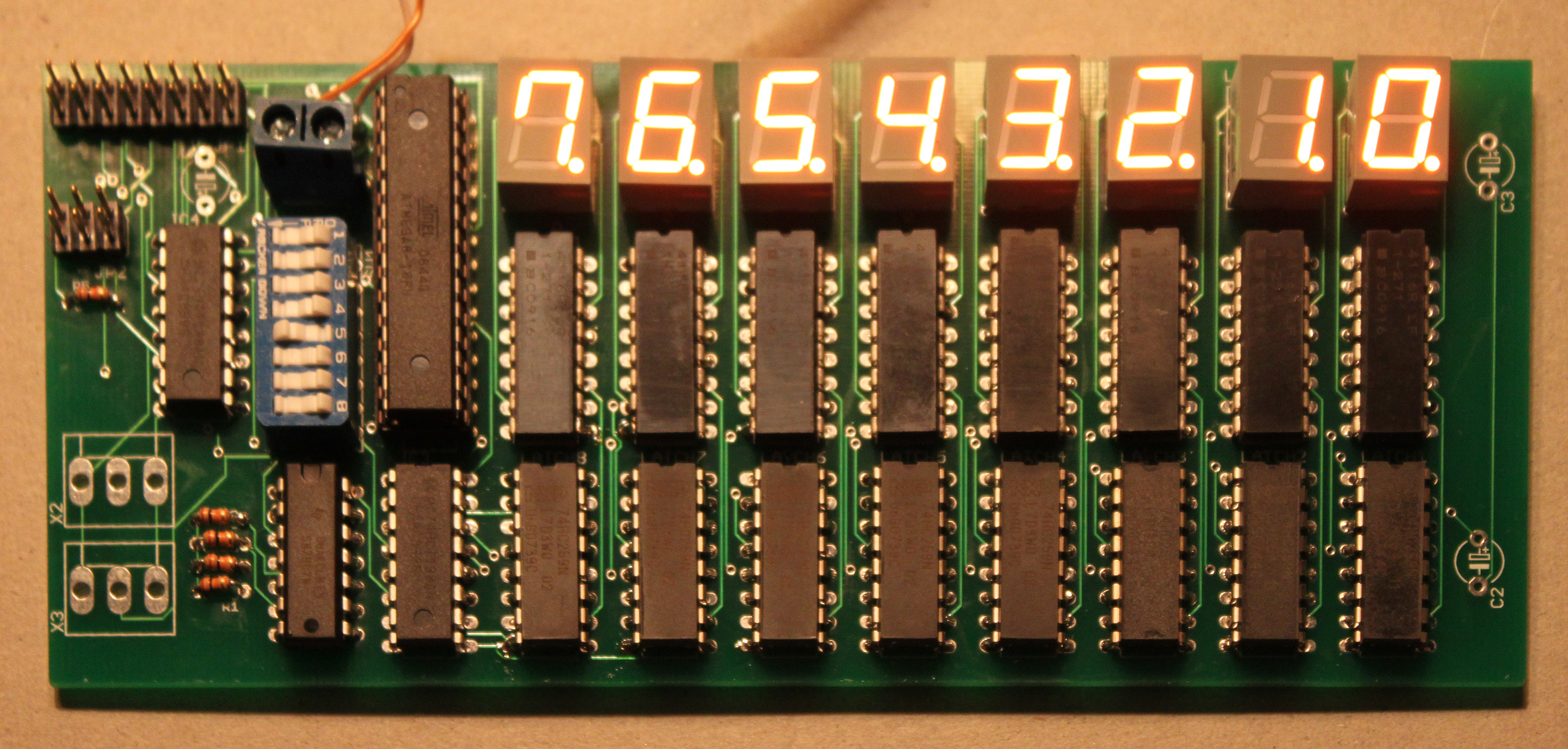
There it is, hot off the Chinese presses -- v1 of the Rocket Panel Printed Circuit Board! I soldered all the components on, loaded the digit-identifying program onto a new microcontroller, popped it in, and turned it on. It worked on the first try! Isn't it beautiful?
 But wait, there's more! I soldered half of a second board together (alas, I had only 4 LEDs left) and put together a 16-pin ribbon cable a few inches long. I connected the two bus connectors and -- voila! Both boards are being controlled by a single processor! As if that wasn't all cool enough, the programming header works, too! I was able to put new code on the microcontroller in place by just running a cable from the programming kit board to the programming header on my PCB. Total success! There was one minor board bug I discovered even before receiving the boards: a wire I was supposed to connect, but didn't, that's needed to read from analog dials. But that's easy to manually fix. Despite the fact that (amazingly) these boards work, I think I'm still going to order the v1.1 boards. They have lots of nice features, such as mounting holes, support for larger LEDs, support for 6 dials rather than just 2 (important because of our joystick, as I described on Sep 16th), and some other odds and ends. Still on the To-Do list:
Can you believe I'm running out of solder? That's like running out of baking soda. I think I've had my current spool of solder since I was in college.
Solenoid valves Friday, September 18, 2009 -- jonh
September 16, 2009 Wednesday, September 16, 2009 -- jelson
One motivation for doing this is that Jon I were scheming today a way to attach a joystick (which is basically 2 pots attached to a lever) to the microcontroller. As the pilot moves the joystick, the microcontroller outputs will electrically control the solenoid air valves that actuate the thrusters and paint-shaker. I'll write more on this once we flesh it out. I'd hoped that the 2nd batch of PCBs would have only tiny revisions compared to the first, to minimize the chance of introducing new bugs. But the changes are pretty substantial at this point. Oh well!
More paint Tuesday, September 15, 2009 -- jonh
Jeremy convinced me to buy from ebay a set of five electrically-triggered solenoid valves, to enable the electronics system to control the various pneumatic functions. His argument was that I'd spend almost as much rigging them mechanically anyway, and that once I attached the valve, everything on the "electrical side" becomes his problem. :v) Tuesday, September 15, 2009 -- jelson
One feature I added to the PCB at the last minute was a couple of headers for analog inputs. Each header has 3 wires: power, ground, and a line back to one of the controllers' ADC inputs. I hoped that by attaching those three leads to a potentiometer, I'd be able to read the position of a dial. Unfortunately I didn't actually get a chance to test this before sending the PCBs out to be produced. I ordered a bunch of panel-mount 50k pots that arrived yesterday, and scrounged a rocket-looking knob out of the hardware lab at work. This evening I tried hooking them up to my proto-board, and wrote a few lines of code that would read the analog input once every 50msec, scale it to a value from 0 to 99, and display that value on the two LEDs on my protoboard. Amazingly, it worked (almost) without a hitch! (The only hitch: the ADC input I was using is the same pin as one of the general purpose input/output pins. I had set all I/O pins as output pins, so a low value was being asserted on the same pin the ADC was trying to read, and always returned 0 -- except when the pot was at such a high value that it overcame the internal resistance of the output pin. When I reconfigured the GPIO as an input pin, everything worked.)
 Paint PaintMonday, September 14, 2009 -- jonh
 A Simulator A SimulatorSaturday, September 12, 2009 -- jelson
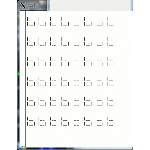
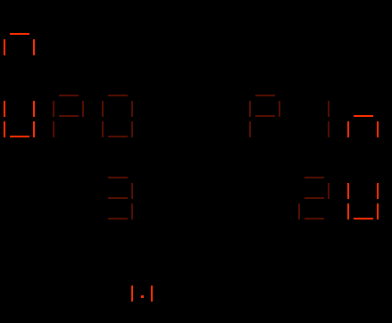
Sure, the hardware's not here yet. But, since when is a lack of completed hardware an excuse not to work on the software? I spent an hour or two writing a little Rocket Panel Simulator that runs on the console under Linux. It's essentially just a display module that I can link against the same code that goes on the real rocket. When the code is compiled in simulator mode, the functions that assert real I/O pins are replaced with functions that interact with my simulator module. To the right is a screenshot of the simulator, configured to display 6 8-digit numbers, running the digit-identification program. I also made some minor updates to the schematic and board layout yesterday. Primarily, I corrected the footprint of the dial connectors. Since the real footprints are smaller, there was also space to add a 3rd one. I also found the connectors at DigiKey that match the templates I used on the v1 boards. If the boards actually work, I may as well just buy the connectors that fit on the boards instead of doing something hacky.
More primer Friday, September 11, 2009 -- jonh
 PCB Layout v1.1
Thursday, September 10, 2009 -- jelson
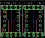
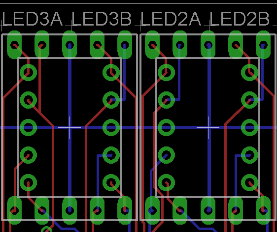
The biggest difference in v1.1 is that the board now supports two different sizes of 7-segment LED displays. The original board only supported 0.39" high digits, because they're cheapest. But there are a couple of models of cheap 0.56" high digits too, which, being bigger, are naturally cooler. For maximum coolness, we really wanted to be able to mix up the sizes -- have a wall with digits in a variety of colors and sizes. But, for simplicity, we only wanted a single board, so our idea was to have a board that has two sets of mounting holes (and associated traces), fitting both sizes. This version of the board now has this feature. It mainly required learning how to extend the parts library in my PCB design software, since this particular type of 7-segment display wasn't in its pre-defined library. And, hats off to Lite-On, the manufacturer of these LEDs. Their pin layouts really makes board design a lot easier. One, their two anode pins are 3 and 8, which are the middle pins in both rows. This means two good things: first, the supply line can run horizontally all the way across the board, without any turns. Second, you can mount LEDs upside-down, which is useful to make a clock (mounting every other digit upside-down gives you a series of colons, rather than decimal points). Also, even though their 0.56" LEDs have horizontal rows of pins, rather than vertical as in the 0.39" version, the segments are controlled by pins in the same quadrant, making the superimposition I was trying to do quite easy. And the supply lines end up being simple vertical tendrils off the long horizontal supply line for the smaller LEDs. The extra traces were all quite short and didn't intersect with each other. At right is a screenshot of two adjacent digit positions, each of which is a 0.39" and 0.56" LED superimposed so that either can be mounted. I learned lots of other new features of my schematic editor, which let me do other cool things:
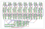
I also blew another $75 at DigiKey today, getting enough ICs to build 3 fully-populated 8-LED boards (when the v1.0 PCBs arrive), and some other odds and ends. In particular, 4 electronic potentiometers so that the microcontroller can control the needle on a car gauge, and some manual knob potentiometers so the kids can twirl some knobs. I have a board design in mind to support the gauges, but that'll have to wait for another post. Here's the latest schematic and board layout, both with and without the traces visible.
Sunday, September 6, 2009 -- jelson
The next step was to try getting a board manufactured. I redrew my schematic using different software, Eagle, that made it easier to go from a schematic to a physical board. I also added a few other features:
 I learned that it takes a lot of tweaking to get the board nice and compact. Early versions were way too spread out. Partly this was because Eagle's default minimum clearance between traces (i.e., the number of "wires" you can pack into a space) was conservative: 1/20'' (50 "mils") between traces. But, the board manufacturers I found claimed they could make boards down to 8 mils; the board got much smaller when I switched Eagle to using a 10 mil routing grid. I also tried to keep the wires from crossing where I had freedom. For example, the resistor ICs are symmetrical; you can go in on the left and come out on the right, or vice-versa. I had each wire enter the resistor on the same side as it exited the latch. Finally, I ended up with a nice, compact board!   Exciting stuff! I sent this off to a PCB manufacturer in China called OurPCB and should have the boards back in two weeks or so. I'm getting 10 boards for $110. There's a $50 setup fee and $40 shipping; the boards themselves only cost about $2.50 each! Of course, if there were no shipping or setup fee, I'd make one board, see if it needs a correction, then get more. But since the boards themselves are such a small part of the overall cost, it's more cost-efficient to just order them all up-front if there's even a small chance they'll work. So I ordered 10. Keep your fingers crossed!  Primer PrimerSunday, August 30, 2009 -- jonh
Weld-on tabs Sunday, August 23, 2009 -- jonh
 Window screen Window screenSaturday, August 15, 2009 -- jonh
Entry rope ladder Saturday, August 8, 2009 -- jonh
We cut up some 3/4" steel stock and drilled them to make rungs for our "rope" ladder, and made the weld-on tabs that the ladder will hang from.
Anti-rust Sunday, July 26, 2009 -- jonh
Rust Saturday, July 25, 2009 -- jonh
I have no idea what made the chemistry go so horribly wrong. I wire-wheeled much of the light layer of orange stuff off, but with all the surface area of the expanded steel, and lots of tight corners, I pretty much destroyed the wire wheel. I decided that it would have to do, and laid down a thin coat of primer over most of the surface with a spray gun. Twenty minutes later, it began to rain. Sheesh. 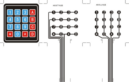 Adding a Keypad Adding a KeypadMonday, June 1, 2009 -- jelson
Of course, as soon as he said this, I realized he was right. So I added another new feature: a 16-key membrane keypad, pictured below, that I bought on Ebay for $3 directly from some random electronics house in China. In fact, I bought two of them, since shipping was $4 no matter how many you buy. I'm not sure yet exactly how the toy will actually work; maybe if you push "A" and then punch in a number, a row of digits labelled "A" takes on that value and starts counting up or down. Or something. But, hey, the Apollo missions flew to the Moon using just a keypad and some rows of 7-segment LEDs so I'm sure I can do something at least as awesome.
So, the procedure for scanning the keypad is
The assignment of signal pins to positions on the bus connector is arbitrary. I reasoned that if I assigned the pins carefully, I could just plug the keypad right into the bus connector, and not even use any extra GPIO lines on the microcontroller. I assigned 8 address lines to the first row, and made sure the Enable pin was on the second row. I figured that as long as I kept the Enable pin un-asserted, I would be able to twiddle the other output pins in order to scan the keypad without affecting the state of the latches. I thought this was a clever way to conserve microcontroller IO pins.
To fix this, I updated the schematic to bring 4 dedicated input pins out to the first row of the bus connector, and move four of the outputs to the second row. Of course, there was no way I was going to update the physical wiring to test this...the test will have to wait until the prototype PCB arrives. In the meantime, to test the scanning procedure, I changed the software to display the key pressed for 3 seconds after the key is released. That is, I could press "5" (the display failed while the key is pressed), and after releasing the key see "5" appear on the display for 3 seconds. Yay!  The gantry The gantryMonday, June 1, 2009 -- jonh
 The Second Prototype The Second PrototypeMonday, May 25, 2009 -- jelson
The first step was to draw a real schematic; this was starting to get too complicated to keep everything in my head reliably. 
Next I laid out all the components on the protoboard to get a sense for how they'd all fit together. This required working out a bunch more details, like finding a DIP switch, power connector, a connector for the control bus (and mating ribbon cable and socket), and a socket for the microcontroller (so I could swap it in and out, instead of soldering it permanently). I also switched from the individual wire-lead resistors to IC-shaped resistor chips -- basically just 8 resistors in a 16-pin package. 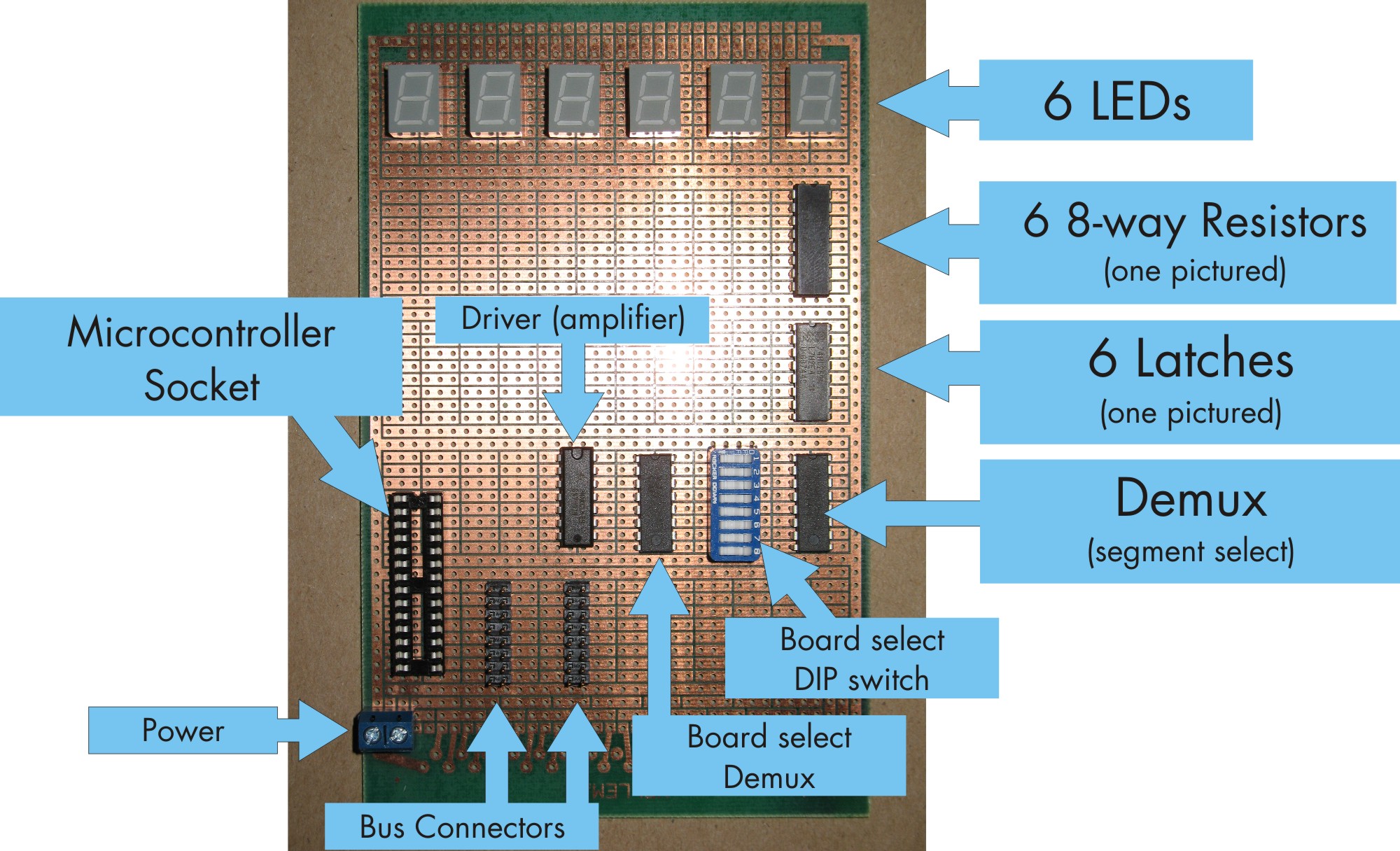 I soldered the components in, and, following my schematic, started to painstakingly make all the electrical connections. The process of cutting a wire to the right length, stripping the ends, and soldering it in is surprisingly time-consuming. It took many hours over several evenings, after which I'd only fully connected 2 LEDs. I decided there was no point in continuing. A board with 2 digits was complete enough to test what I wanted to test. I'd test with a 2-digit board and let a PCB manufacturer do the hard work of running every wire to a fully populated board. 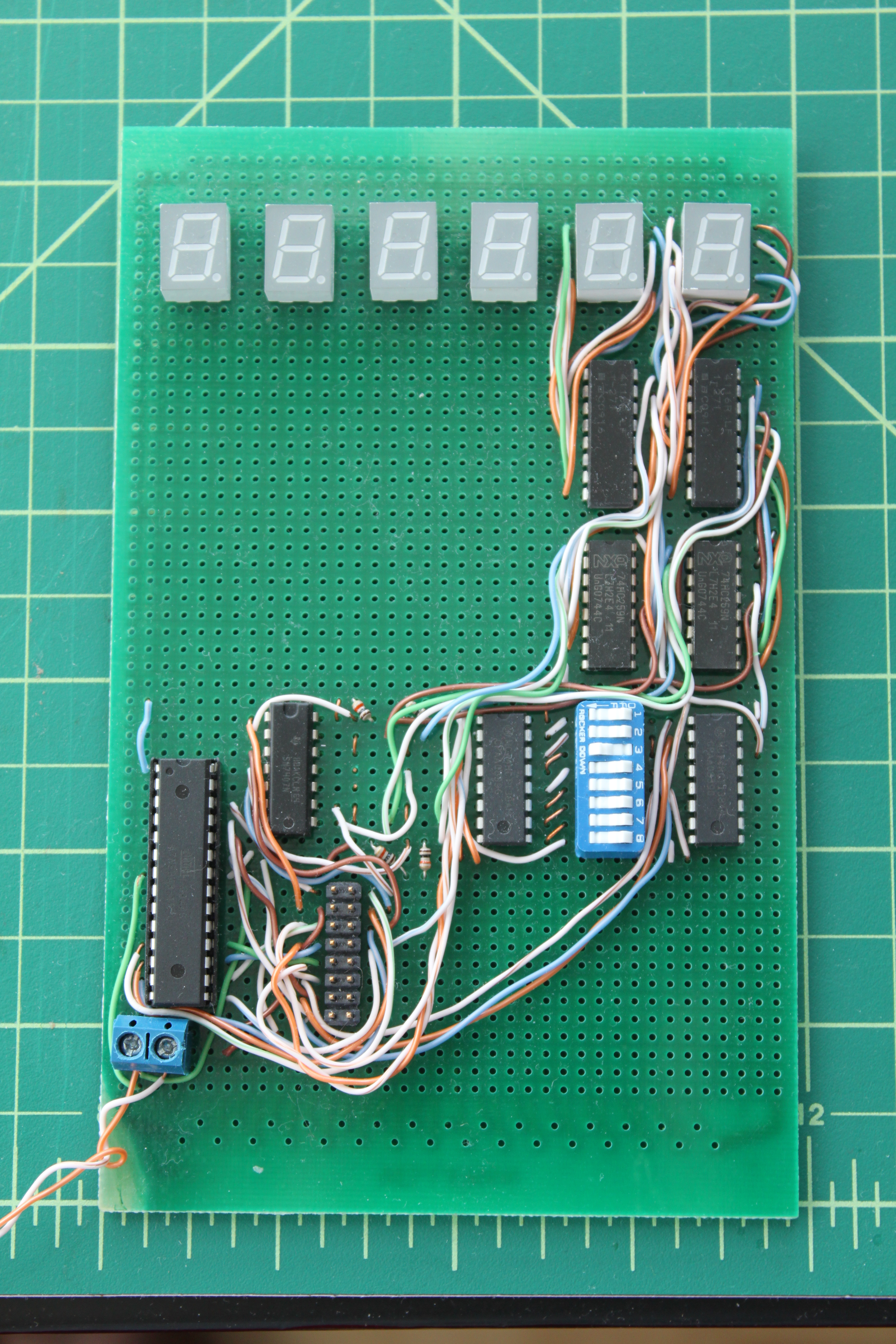 I turned the thing on and was sad to discover it didn't work. After a while with a voltmeter, I concluded the driver wasn't working properly. Of course, the real problem was that I didn't understand how it was supposed to work. I'd thought that if you put a voltage in (low or high), the same voltage would come out. Not so: it's what's called an "open collector" driver. That means if you put in a low voltage, a low voltage comes out, but if you put in a high voltage, nothing comes out; the circuit is open, and whatever's on the other end just floats. The fix ended up being easy: I attached a pull-up resistor to each of the four outputs of the driver. Then it worked! Next, I wrote a test program that commands all 64 LEDs in the entire board stack to identify themselves once per second. For example, LED digit 3 on board 5 is told to display "b...5...d...3". This test served two purposes. First, it let me test the board-select circuitry. As seen in the video below, if use the DIP switch to configure the board as Board 2, the right most digit says "b2d0". Then, if I change it to Board 4, it starts to display "b4d0". Cool -- it worked! The test was also useful because it shows the microcontroller (running at 1MHz) has plenty of time to individually program all 512 segments (8 segments x 64 digits) with no visible delay.
Tuesday, May 12, 2009 -- jelson
The last time I'd tried to use an LED was when I was about 15 years old. I was really into electronics back then, but didn't have any good reference texts. One day, I saw a 7-segment LED in Radio Shack and thought "Wow, that would be cool to use!". It seemed simple enough: 7 individual power pins, one for each segment, and one common ground pin. I figured if I just attached a battery across the two, it would light up. I took it home and, unfortunately, couldn't get it to do anything. 20 years later, I started reading about LEDs and learned my problem: I had assumed that an LED was a resistive load, just like a light bulb. It turns out, diodes are magical things that cause a voltage drop but don't provide resistance. If you attach a battery directly across a diode, it's no better than a short circuit: the diode will immediately burn out. The right design is to add a resistor, chosen so that the current flowing through it, taking into account the voltage drop inherent to the diode, is no more than what the diode says it can take. My plan was to run the system at 5V. The LED data sheet said that the diode drop was 2V. That leaves 3V "visible" to the resistor. My target was about 10 mA per segment so I picked a 300 ohm resistor (actually, 270: the closest value I had in stock).
My first test was simply to attach an LED segment to a 5V power
supply and a resistor, to see if it would light up:  Wow! This was exciting. I'd already done way better than 15-year-old Jeremy! Next I decided to try out a latch. I attached two segments of the LED to two of the latch's outputs (with resistors in between). Then I attached three buttons to the latch: one to the data input pin, one to the lowest bit of the "segment select" address line, and one to the Enable pin. And I finally learned just how to use pull-up/down resistors: you attach a high-value resistor to, say, a pin and ground. Then, on the pin side of the resistor, attach a push-button tied to Vcc. When the button is not pressed, the resistor (with no current flowing) keeps the pin at ground. When you push it, you tie it to Vcc instead; the resistor is so strong that the connection to ground is overcome. If I pushed Enable without pushing Data, the segment would go out. If I hold down Data and then push Enable, it lights up. If I did all of this while holding down the Segment Select line, it would happen to segment #2. 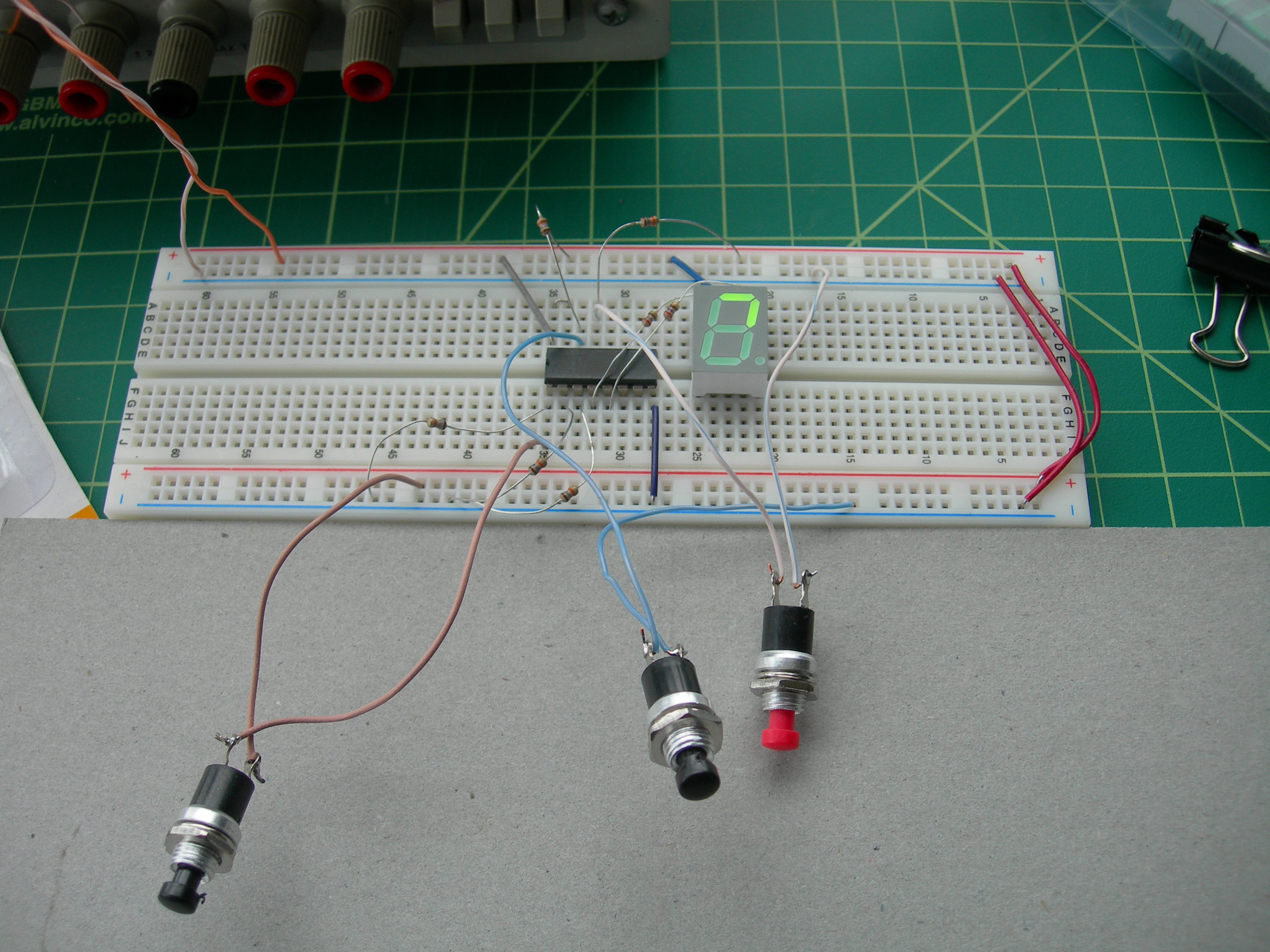 I couldn't believe this was all working! I decided the next step was to get the microcontroller to flip the lines automatically, rather than me doing it manually with buttons. I hooked up all 7 segments to resistors and to the latch, and figured out how to use my new microcontroller programming kit. I made a table defining which of the seven segments should be lit up for each number 0-9, and each letter A-Z. (Some letters, like W, X, and Z, can't actually be represented by these displays.) Then I wrote a program having the controller cycle my LED through the all the numbers and letters. It worked! Next I added a second digit and a second latch, and a first demultiplexor that would let me select which of the two digits I was controlling. The circuit was really starting to take shape now: I had a real data bus, and real segment-select bus, even though there were only two devices on each bus. 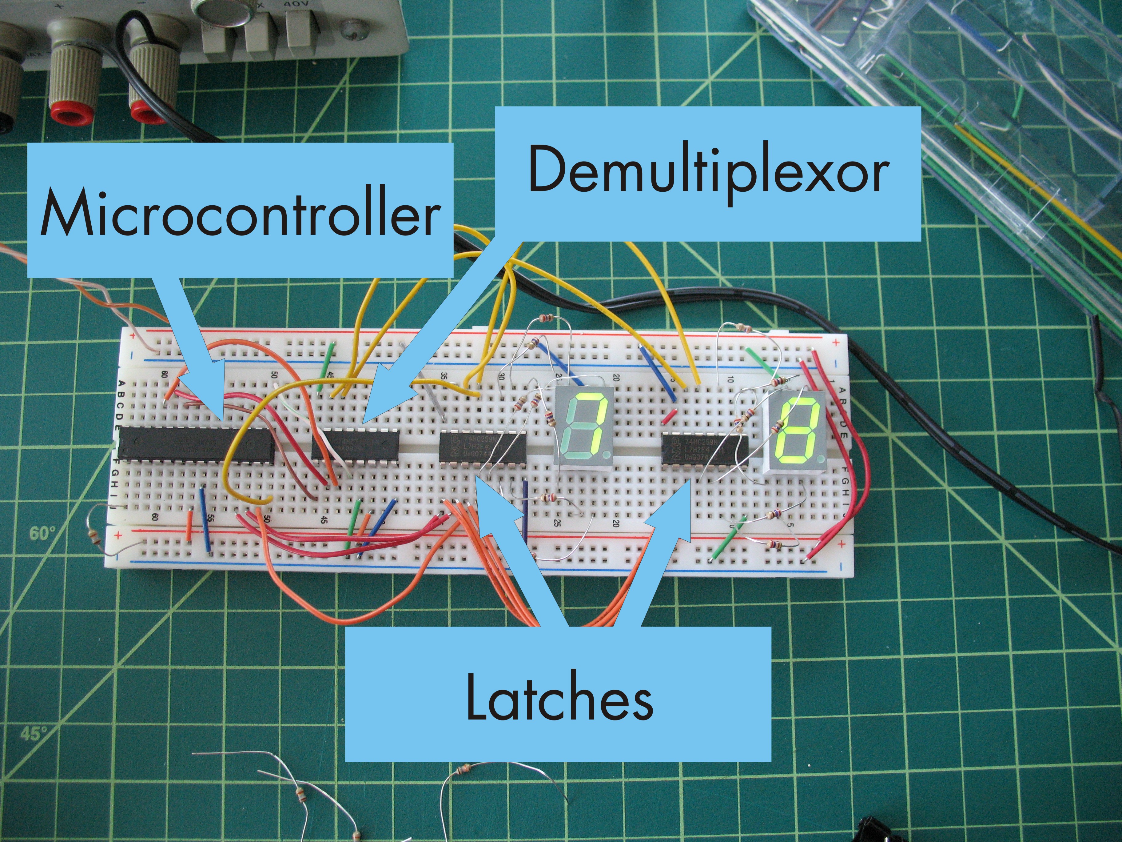
Thursday, April 2, 2009 -- jelson
Luckily, I ran this plan past my friend Lew before going any further. He knows electronics pretty well, and suggested what I needed were some latches. A '259-model latch is a basic memory device; it can remember 8 bits, and asserts those values on 8 output pins. To change them, you twiddle 5 inputs: first, assert 3 address lines, to tell it which of the 8 outputs you're trying to change; then, assert 1 data line, to tell it what value that output should take; then, "strobe" (i.e., go through an asserted/unasserted cycle) the Enable line. So, by attaching each of the 8 segments of an LED digit (including decimal point) to the outputs of a latch, it's possible to control all 8 segments using just 5 control lines -- the latch's inputs -- instead of 8. But, more exciting is that this scheme scales well. If I want 24 digits instead of one, I need only 28 GPIO pins: the three address lines and one data line can run on a common bus, shared by every latch. 24 GPIO lines are then needed for each latch's Enable pin, letting us specify which latch we're actually talking to; the rest ignore the address and data lines because they're not being strobed. That is, we can program a latch by asserting the segment number on the three shared address lines (which I'll now call segment select), asserting the value of that segment on the shared data line, and then strobe the one (out of 24) Enable lines corresponding to the digit we're trying to change. But wait! We can do even better! Another clever device, called a demultiplexer, can reduce our pin requirements even further. '138 series demultiplexers take 3 address lines and one Enable line as input, and have 8 outputs. Unlike a latch, a demux only asserts one of its outputs at a time. When we strobe its Enable line, it strobes whichever of the 8 output lines we've selected using its 3 address inputs. Now, controlling 24 LEDs requires even fewer control lines: we can attach each LED to a '259 latch, with a common bus for the 1-bit data channel and 3-bit segment select, then attach each of the latch's Enable pins to one of the outputs of a demultiplexer. For 24 digits, we'd need 3 demultiplexers, 8 latches on each. Of course, the addressing input lines of the demultiplexers can also be shared. I will now call these shared address lines digit select. Then, connect each of those 3 demux's Enable lines back to the microcontroller. Now we can control each of the 8 segments of 24 LEDs using only 13 GPIO pins: 1 data line, 3 segment select lines, 3 digit select lines, and 3 pins that lead back to the Enable pins of the 3 demultiplexors. But wait! We're still not done! Now we can add a 2nd layer of demultiplexors. In other words, have one "top-level" demux, and attach each of its 8 outputs to the Enable lines of 8 more demux's. I will call the 3 address lines of this top-level demux the bank select lines. Each of the 2nd-level demux's can control 8 digits, so this is now a total of 64 digits, each with 8 segments (or a total of 512 segments) that can be individually controlled with only 11 output lines on the microcontroller: 1 data lineAwesome! And suddenly I more deeply understand how a computer's memory bus works. Unfortunately we're not quite done. When I showed this plan to my friend and colleague JD, he pointed out a problem. The data and segment-select lines have a rather large fanout: the microcontroller asserts just one data line and it is taken as input to all 64 latches. Most parts are spec'd for a maximum fan-out of 10 or 15. So, we also have to add drivers -- basically amplifiers -- one for each of the 8 banks. That is, the microcontroller asserts data and segment-select lines to 8 drivers; each driver re-asserts it to 8 latches. While the design seemed reasonable, the idea of assembling such a beast did not. Such a board would have hundreds of signal lines and close to 5,000 tiny holes that would need precise drilling. It didn't seem reasonable to try and fabricate it myself. I'd have to learn another new skill: how to draw a schematic and have a PCB professionally manufactured from it. Board manufacturers charge by the square inch. We wanted the rows of digits to be spread out (leaving room in between for things like labels, dials, etc.), so I added one final feature to the design. Instead of one huge board with all 64 digits on it, I'd make 8 smaller, identical boards, with their 11 magical lines all connected to each other using a ribbon cable. I'd give each board a DIP switch that would let me tell it which "bank number" it was. I should then be able to put a microcontroller on one of the boards -- it doesn't matter which -- and let the ribbon cable distribute its 11 outputs to all the others. Then, we'd be able to manufacture smaller boards in larger quantities, rather than one huge board. Plus, it has the significant advantage of letting us spread the numbers out in the rocket ship a bit more. With all this decided, I drew up a basic block diagram showing what each board would look like. I was so excited: the project was already paying for itself in teaching me new things! 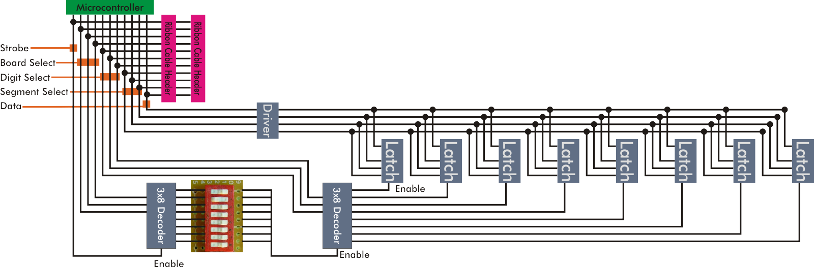 The diagram above shows the latches, but doesn't depict the LED or resistors attached to each latch. Also, it shows my cheesy board-select method: each output of the first-layer demux is attached to one switch in a bank of 8 DIP switches. Then all the outputs are bussed together. So, to select (say) board 4, you turn on switch 4, and turn all the others off. With some more complex logic, I could have made it work in binary (allowing you to select 256 boards), but this thing was already complex enough and other aspects of the design limited us to 8 boards per stack anyway. My next task was to pick a microcontroller. The first sub-task was to pick a brand of microcontroller. My only past experience with them was tinkering with some PICs with my friend Guy back almost 15 years ago. (Aside: We'd tried to build a board we could install in his apartment's front-door intercom so it would unlock the downstairs door if someone pushed the buzzer with a secret morse-code pattern. We hacked together an assembly-code program that seemed to do the right thing on a test board: lighting up an LED for a few seconds when we pushed a button in the right pattern. But it never worked when we actually installed it. Guy's dad, an electrical engineer, suggested a few changed, including "pull-up resistors", which neither of us had heard of at the time and had no Google to help us, so the project fizzled.)I spent a day or two comparing Atmel, PIC, TI and a few others, and finally decided on Atmel. I liked them most of all because they're open: with a gcc-based toolchain and open-source C library the environment felt comfortable. Though I wasn't expecting to write assembly language, the instruction set for Atmel's microcontrollers seemed much easier than PIC's somewhat bizarre and tortured design. The Atmel has 32 registers -- more than my desktop machine has! The PIC is so weird that GCC can't even target it. The PIC's development board seemed a little better (cheaper, and USB rather than serial-port based), but ultimately I decided on Atmel. The microcontroller I picked was the Atmel Atmega8, an 8-bit microcontroller with about 20 digital I/O pins, as well as some analog-to-digital converters, which will come into play later in the story.  The brute force redesign The brute force redesignWednesday, April 1, 2009 -- jonh
Somewhere along, it occurred to me that my prior plan had some unnecessary conditions: aluminum bend and rivet construction, an understanding of actual engineering. But this structure isn't actually going to get launched anywhere. Weight is not a consideration. Why not relax those constraints? How about I just weld together a rigid steel frame, rivet the aluminum onto that, and be done with it already? With this new freedom, I broke out my python 3D model again. I built a simpler model, a series of tapered hexagonal prisms. It looks more rocket-y, less lunar-lander-y. In the model here, the the opening in the lower section is the "door" hatch, and the opening in the upper section in the "window" (to let in a reasonable amount of light for play). The topmost cone also hinges up. The design called for creating in-plane quadrilateral surfaces on the metal frame, so that each aluminum panel can be riveted along all of its edges. Father-in-law Dick pointed out to me that the hack welder uses square tube, because it makes all the joints so much easier to assemble. So I designed each face to consist of three segments of tubing that share a plane with the corresponding aluminum panel. The fourth edge of the panel lines up with the (tilted) corner of the tube for the adjacent face; so a strip of steel is welded onto that tube to complete the quadrilateral. This made for a minimal number of components. The next challenge was figuring out how to cut the correct angles on the ends of the tubes. I'm pretty good at working out the side-length trigonometry for the wire frame, but those compound angles really made me dizzy. I had a bill-of-materials spreadsheet that converted coarse measurements ("bottom segment has radius 24 inches") into lengths and quantites of square tube. I extended it to also tell me what compound angles to cut on the end of each tube. The math was hard enough that I was still unconvinced that it would work on real metal, so I then built a little python script that simulated the effect of each cut on the miter saw, and emitted a PostScript page that cuts and folds into a paper model.
I dropped a couple hundred bucks on steel at Everett Steel. I suppose this is a good place to go if you're, you know, some sort of industrialist who actually builds things with steel. The guy behind the desk always seemed to be "swamped" with work, in a union-employee sort of way that meant he could talk to me for 10-15 minutes about why he hadn't even pulled my order off the teletype yet. The yard guy, on the other hand, was much cooler; I think he enjoyed the absurdity of putting a few hundred pounds of steel on the roof of my Ford Escort and watching the suspension droop.
From the twisty construction of the lid, I understood my mistake. First, I'd established the angle between the edges on each individual face just by the miter angle cut into the tubes. There was enough error in this angle that, once welded, it was impossible to assemble the final 3D structure to the right shape. Second, it was hard to even hold the six faces together long enough to tack weld them; just too many moving parts. Magnets were no help, since the tubes were never coplanar or perpendicular. So, for the next section, the lower section, I built an 8x8 platform from a couple pieces of plywood and some studs. I screwed pegs down to the panel to make a jig, holding each tube at the precise final-assembly angle, and tack-welded them in place. (I did more than tack weld, until I realized that the smoking plywood was probably interfering with the weld quality.)
Next was manufacturing frames for the door and window hatches, and hinges for those and the lid hatch. This took longer than you'd think for the amount of metal involved. Here's a tip when drilling: clamp that metal down really well, or you'll blast lots of drill bits apart. I welded pairs of tabs where the top and bottom segments meet, so I could bolt them together. Next, I welded 1"-wide strips of 16-gauge sheet metal onto the chassis to complete the fourth (right) edge of each planar face.
Wednesday, April 1, 2009 -- jelson
When Jon first started talking about building a rocket ship treehouse for his kids, it sounded like a static display: other than the shape and the material, pretty much the same as any other treehouse. But then he started talking about features that would make it come alive: pilot-controlled thrusters! A paint-shaker that simulates the rumble of takeoff! I got excited. I told Jon I thought his plans were desperately lacking something. The quintisenntial artifact that screams "1950's-era fictional space program": lots of flashing lights and dials and buttons and beeps. One of the things I've been meaning to do for the past few years is improve my working knowledge of electronics. And, fresh off completion of my automatic closet light, I was ready for a bigger challenge. I offered my services as an avionics subcontractor, and Jon readily agreed. My original idea for the control panel, in April of 2009, was relatively simple: lots of seven segment displays, perhaps 30 of them total, arranged in 6 groups of 5-digit numbers of varying colors. I'd imagined them flashing and counting, a constantly changing sci-fi display of random numbers. As we'll see, I rather dramatically under-estimated the ultimate complexity – and fun – of the project. The avionics ended up being
 The elegant design The elegant designSaturday, December 1, 2007 -- jonh
I wasn't sure the design was going to be big enough to be fun to play in, so I set about building a full-scale model in the basement. Fir strips represented the edges, and zip-ties secured them at the vertices. I built one layer of the structure, and it wobbled so enthusiastically, I couldn't make it stand up. This experience made me doubt my extensive knowledge of geodesic structures (specifically, I had heard of them before), and sort of put the project on hold for a while. (I suspect that, had I completed the structure, it would have been somehow holistically rigid. But the balloon of enthusiasm had been deflated.)
Treehouse origins Wednesday, August 1, 2007 -- jonh
"Have you told Eliot about this already?" I ask, cautiously. "Oh, yeah! He's really excited about it!" says Christina. "Greeeeat." I say, realizing I've been committed. Then inspiration strikes. Unfunded mandate? Fine. "Okay, I'll build a treehouse, but I'm not going to spend a month just to make an ordinary pressure-treated-lumber-and-tar-paper monstrosity. Nope, we're going to Boeing Surplus." Before it closed at the end of 2007, Boeing Surplus was a staple in the Seattle maker world. There was a lot of junk there, but many reports of great finds by the patient scrounger. I live too far away to go often enough to get the really good stuff. But Eliot and I scored four big sheets of really cheap sheet aluminum (some polishing required), a bunch of smaller aluminum shelving, and three 24-foot thick-walled aluminum tubes. We strapped our loot precariously to the roof of the Ford Escort, and drove home on a non-freeway route, to prevent the airplane parts from become airborne before they were made into an aircraft. |
||||||||||||||||||||||||||||||||||||||||||||||||||||||||
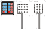
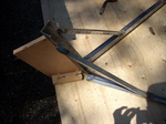
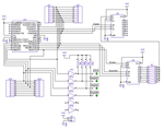
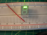

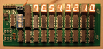

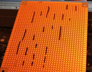 When I got home, I knew things were working well enough that it
was safe to start melting lead.
I had been layout out the protoboard on bus commutes,
so I was ready to start (images at right) placing the sockets,
marking the copper side for selective removal,
dremeling away the unwanted copper,
soldering in the sockets,
and then soldering in the rest of the components.
When I got home, I knew things were working well enough that it
was safe to start melting lead.
I had been layout out the protoboard on bus commutes,
so I was ready to start (images at right) placing the sockets,
marking the copper side for selective removal,
dremeling away the unwanted copper,
soldering in the sockets,
and then soldering in the rest of the components.
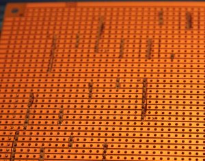
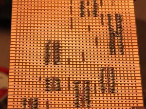
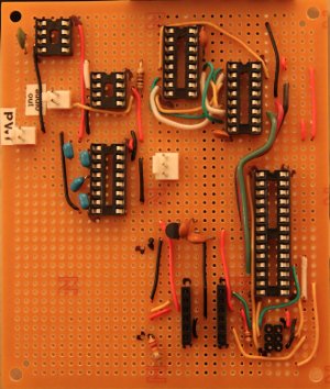
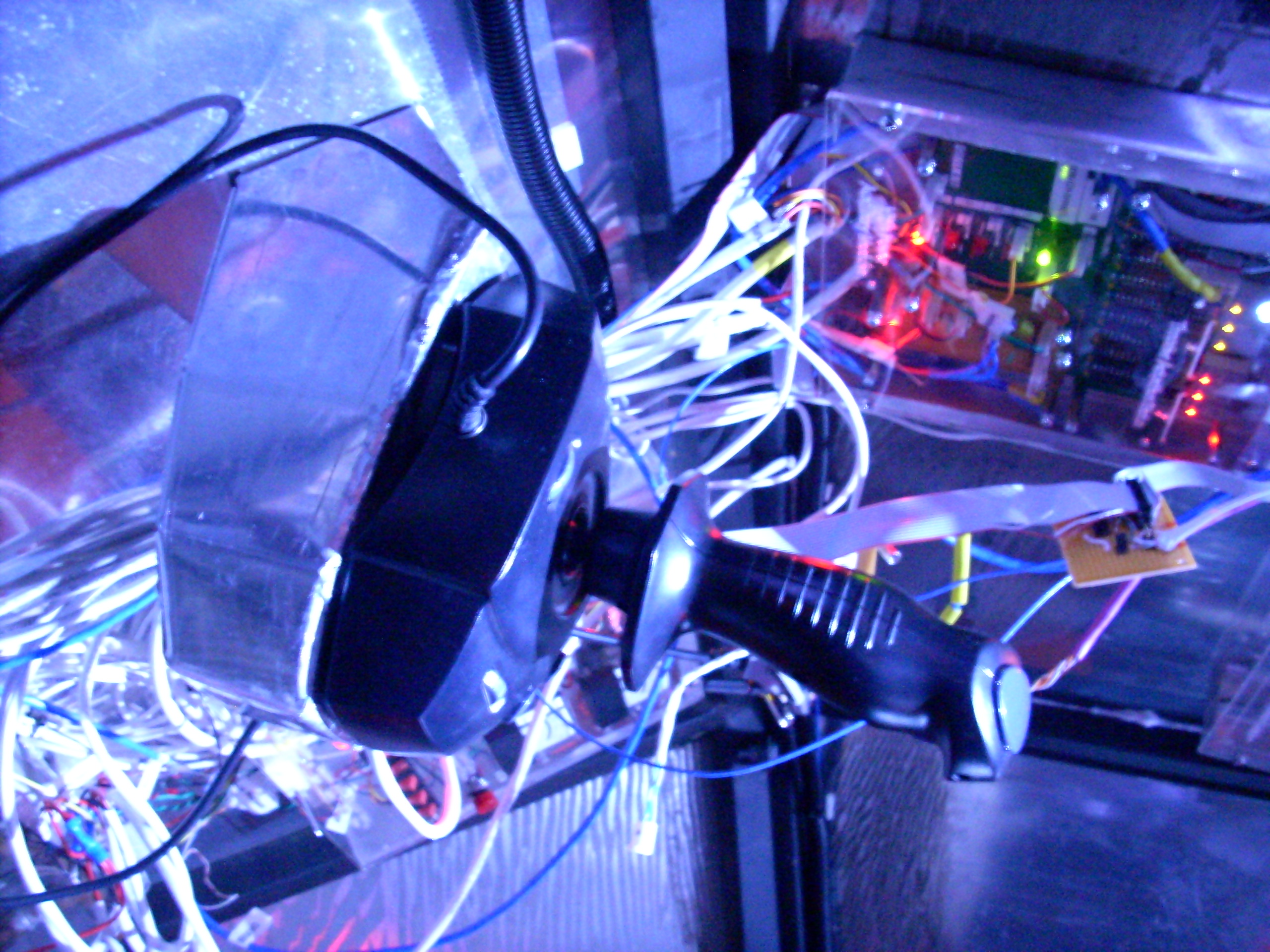
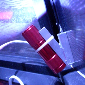
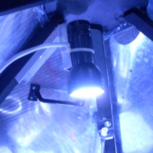
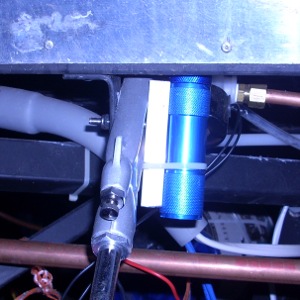
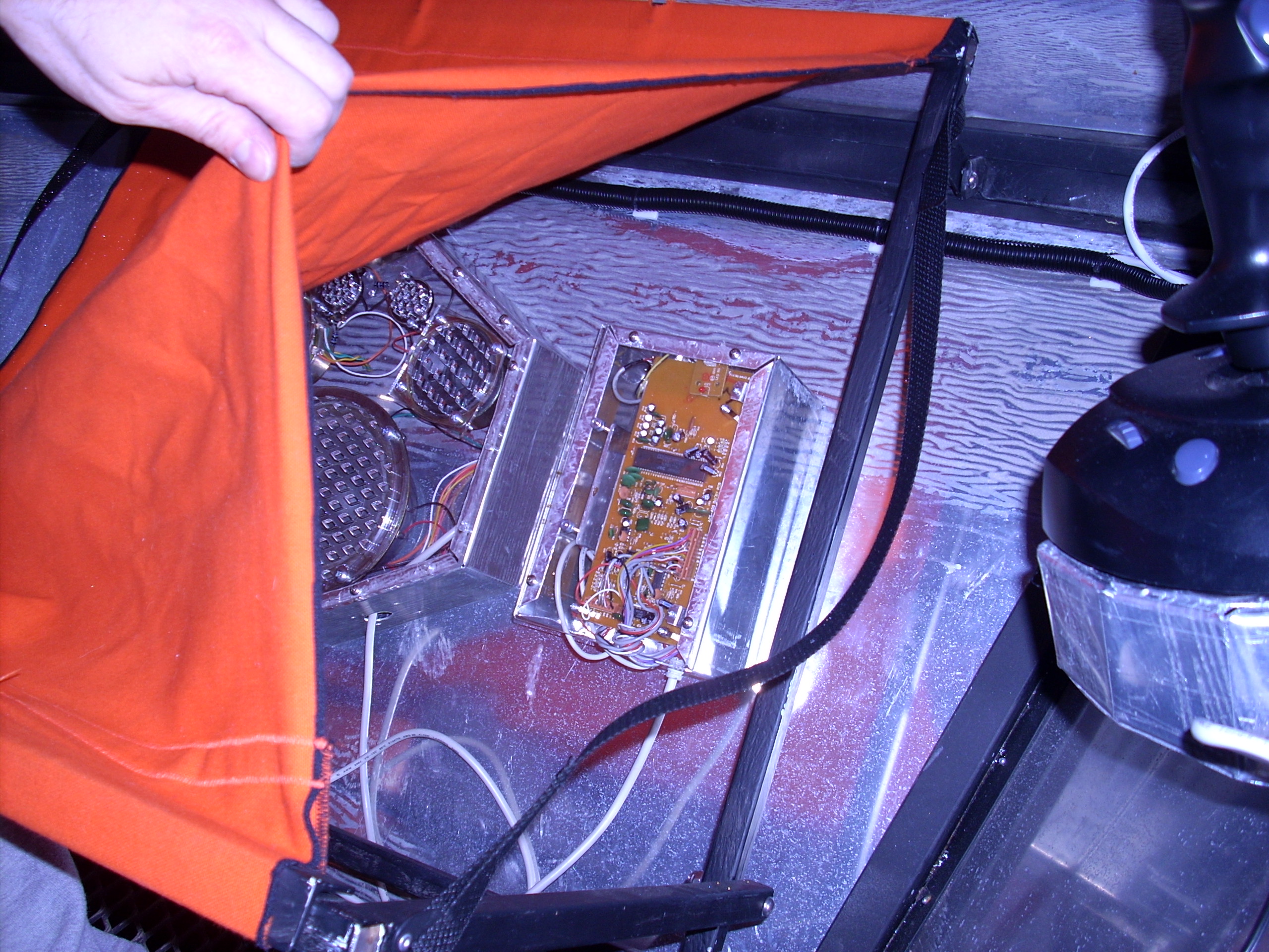
 Tonight, I came home, plugged everything in, strapped in some fabric,
and threaded the machine.
And, just like that, Noa's pixels rendered in threads!
The color scheme on this first one didn't come out perfectly,
and there are a few other little alignment problems and minor bugs,
but overall, it's pretty darn neat!
Tonight, I came home, plugged everything in, strapped in some fabric,
and threaded the machine.
And, just like that, Noa's pixels rendered in threads!
The color scheme on this first one didn't come out perfectly,
and there are a few other little alignment problems and minor bugs,
but overall, it's pretty darn neat!
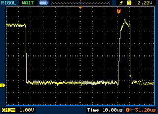
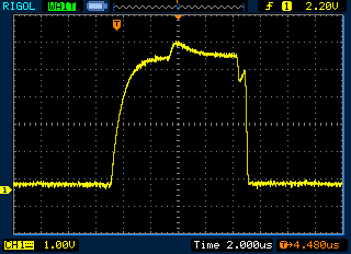
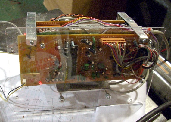 I mounted the stack of three audio circuit boards to their plexi panel.
Then I alligator-clipped a wall wart onto the power input,
plugged it into my computer,
and started playing the
I mounted the stack of three audio circuit boards to their plexi panel.
Then I alligator-clipped a wall wart onto the power input,
plugged it into my computer,
and started playing the
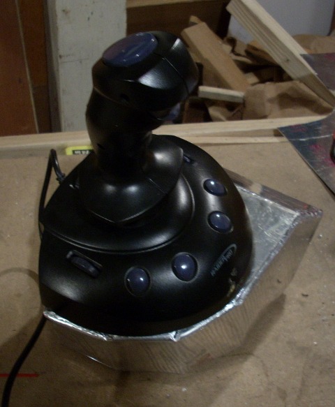 The last thing I got done was the joystick.
I had to take the joystick's guts out,
rotate the handle 180°, and put it all back together.
Then I screwed the joystick to the aluminum mount box.
It looks good; hopefully I didn't break anything.
The last thing I got done was the joystick.
I had to take the joystick's guts out,
rotate the handle 180°, and put it all back together.
Then I screwed the joystick to the aluminum mount box.
It looks good; hopefully I didn't break anything.
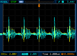 Here, we're running software that pulses all of the address and data
lines (one shown in cyan), but never the strobe line (yellow);
yet you can see the strobe line coupling pretty enthusiastically to
the pulses.
Here, we're running software that pulses all of the address and data
lines (one shown in cyan), but never the strobe line (yellow);
yet you can see the strobe line coupling pretty enthusiastically to
the pulses.
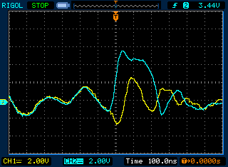 Four volts of enthusiasm, in fact.
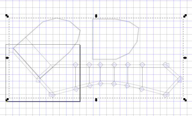
 Jeremy found a chapter in "H&H", the canonical EE textbook,
all about exactly what we were doing:
Jeremy found a chapter in "H&H", the canonical EE textbook,
all about exactly what we were doing:
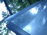 This morning Eliot and I took out the window panel, drilled the rivets,
and installed strips of PVC to help shed water before it leaks inside.
This morning Eliot and I took out the window panel, drilled the rivets,
and installed strips of PVC to help shed water before it leaks inside.

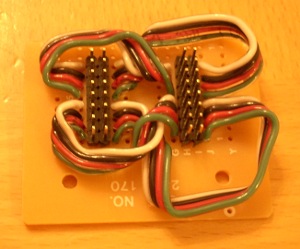 When Jeremy wired the rocket last weekend, he found it easiest to
split the Elson Parallel Bus cable at the entrance to the raster
display. Splitting it is done with a male-to-male header connector.
But, as far as I know, that's not a standard part. As you can see,
it's not a very elegant hand-wired part, either.
When Jeremy wired the rocket last weekend, he found it easiest to
split the Elson Parallel Bus cable at the entrance to the raster
display. Splitting it is done with a male-to-male header connector.
But, as far as I know, that's not a standard part. As you can see,
it's not a very elegant hand-wired part, either.
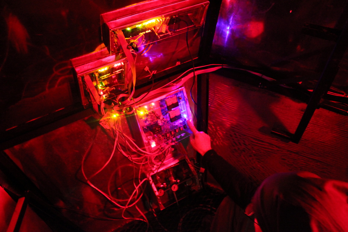
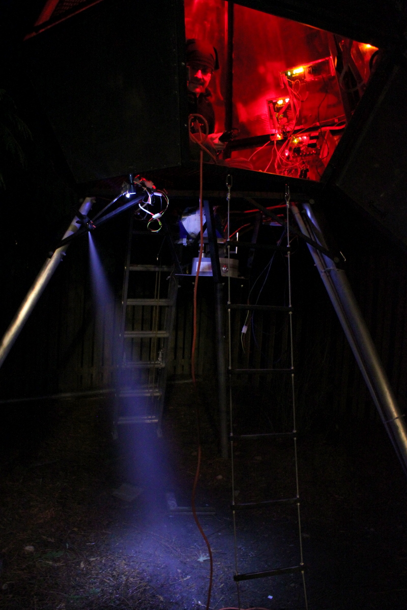
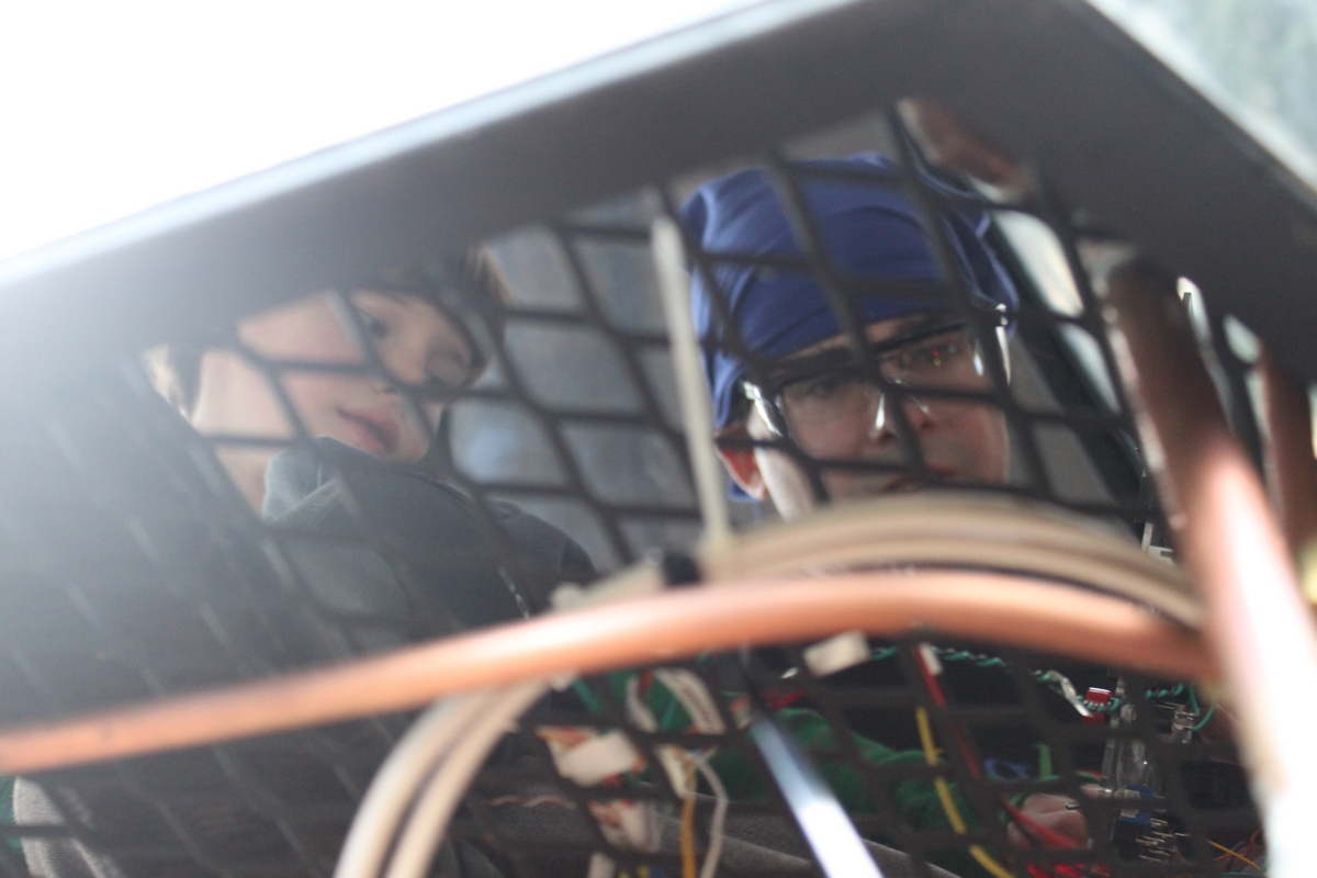 I also built more of the boxes; there are only two left to go.
(
I also built more of the boxes; there are only two left to go.
(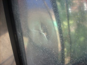 Unfortunately, at one point, Captain Eliot popped open the top hatch
so enthusiastically that it popped out the rivet that holds the limit cable
bracket in place. The hatch continued around its pivot until it impacted
the aluminum skin, cracking it.
Fortunately, the cabin atmosphere leakage through the crack is minimal.
We replaced the broken rivet with a through-bolt.
Unfortunately, at one point, Captain Eliot popped open the top hatch
so enthusiastically that it popped out the rivet that holds the limit cable
bracket in place. The hatch continued around its pivot until it impacted
the aluminum skin, cracking it.
Fortunately, the cabin atmosphere leakage through the crack is minimal.
We replaced the broken rivet with a through-bolt.
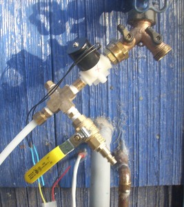 I also replumbed the supply side of the water line,
installing the solenoid valve and a new air-purge valve
to replace the one I damaged by over-torquing it.
I also replumbed the supply side of the water line,
installing the solenoid valve and a new air-purge valve
to replace the one I damaged by over-torquing it.
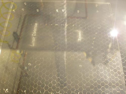
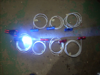 I did get a chance to sneak downstairs and bolt together the couch.
I also cut wire to length and assembled the seven lighting fixtures.
Man, I need a decent soldering iron.
I did get a chance to sneak downstairs and bolt together the couch.
I also cut wire to length and assembled the seven lighting fixtures.
Man, I need a decent soldering iron.
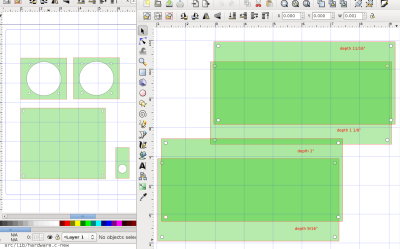 I measured out a bunch of the boards, meters, and switches, and made
Inkscape drawings for laser cutting the plexiglas panels they will mount to.
I measured out a bunch of the boards, meters, and switches, and made
Inkscape drawings for laser cutting the plexiglas panels they will mount to.
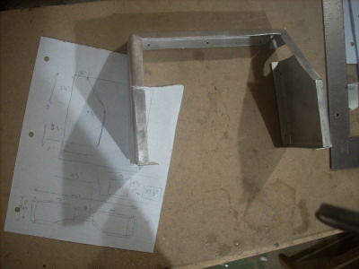 I measured in the rocket for an aluminum box (plexiglas face) to house
the air manifold assembly.
My first try failed in a way I hadn't experienced before:
when I made the first bend in the brake, the metal was very stiff,
and I heard a weird crackling or splintering sound.
I pushed it the rest of the way through the 90 degree bend,
and by the time I was done,
the flanges had cracked along the bend about halfway along their length. Yikes!
I hypothesized that it was temperature related. Seems unlikely -- I mean,
it's been cold around here, but our basement isn't that much colder
than normal.
But I heated up the metal with a torch, and did a few more bends that
came out great. Wild.
So I marked up a new piece of aluminum, cut it to shape, and carefully
preheated each line before bending it, getting pretty good results
marred only on the second bend, where I tried to rush things a bit and
apparently didn't add enough heat.
I measured in the rocket for an aluminum box (plexiglas face) to house
the air manifold assembly.
My first try failed in a way I hadn't experienced before:
when I made the first bend in the brake, the metal was very stiff,
and I heard a weird crackling or splintering sound.
I pushed it the rest of the way through the 90 degree bend,
and by the time I was done,
the flanges had cracked along the bend about halfway along their length. Yikes!
I hypothesized that it was temperature related. Seems unlikely -- I mean,
it's been cold around here, but our basement isn't that much colder
than normal.
But I heated up the metal with a torch, and did a few more bends that
came out great. Wild.
So I marked up a new piece of aluminum, cut it to shape, and carefully
preheated each line before bending it, getting pretty good results
marred only on the second bend, where I tried to rush things a bit and
apparently didn't add enough heat.
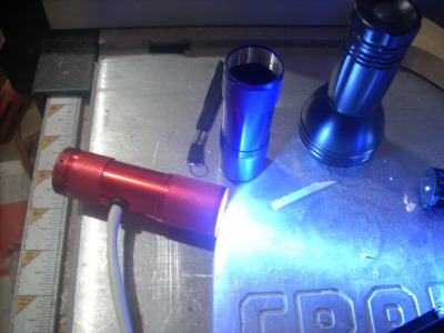 I also figured out how to mechanically wire the flashlights for external power.
I found some grommets that made a tight fit to our power wire.
To connect them, I found I needed to remove the bulb head from the
flashlight body tube. This I achieved by the graceful method of slipping
the flashlight over a piece of 1/2" PVC pipe, setting a block of wood
on top, and giving it a whack with a hammer.
After the switch-and-battery-ectomy, the new light has an attractive fixture
and I think will retain its waterproofness.
I also figured out how to mechanically wire the flashlights for external power.
I found some grommets that made a tight fit to our power wire.
To connect them, I found I needed to remove the bulb head from the
flashlight body tube. This I achieved by the graceful method of slipping
the flashlight over a piece of 1/2" PVC pipe, setting a block of wood
on top, and giving it a whack with a hammer.
After the switch-and-battery-ectomy, the new light has an attractive fixture
and I think will retain its waterproofness.
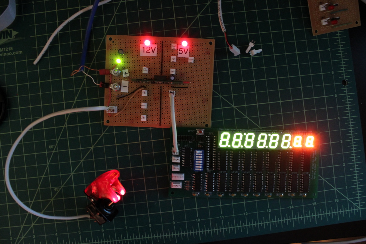
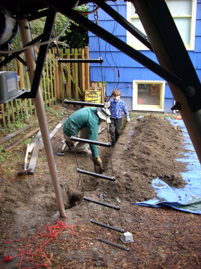 The cold front finally passed this afternoon.
Eliot's been eagerly waiting to help dig the trench.
Evan helped a bunch, too.
I expected to have to route under a couple tree roots, but I was
completely unprepared for one major treeway interchange we found.
The choice was to settle for about a 5" burying depth, or keep digging.
After an hour on hands and knees, we finally broke through our own little
subterranean viaduct.
I'll have to solder the pipes in situ,
since the tunnel is too narrow to push a joined pipe through,
and the pipe has to take a quick turn to avoid the next root underpass.
The cold front finally passed this afternoon.
Eliot's been eagerly waiting to help dig the trench.
Evan helped a bunch, too.
I expected to have to route under a couple tree roots, but I was
completely unprepared for one major treeway interchange we found.
The choice was to settle for about a 5" burying depth, or keep digging.
After an hour on hands and knees, we finally broke through our own little
subterranean viaduct.
I'll have to solder the pipes in situ,
since the tunnel is too narrow to push a joined pipe through,
and the pipe has to take a quick turn to avoid the next root underpass.
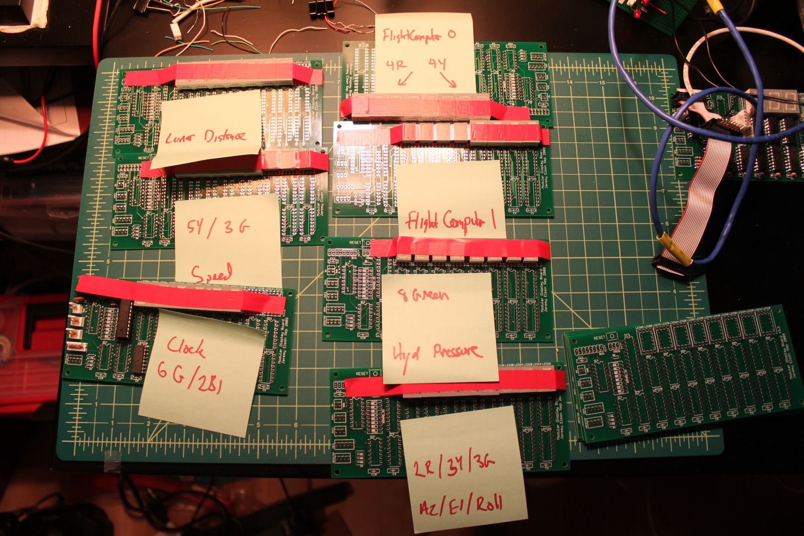

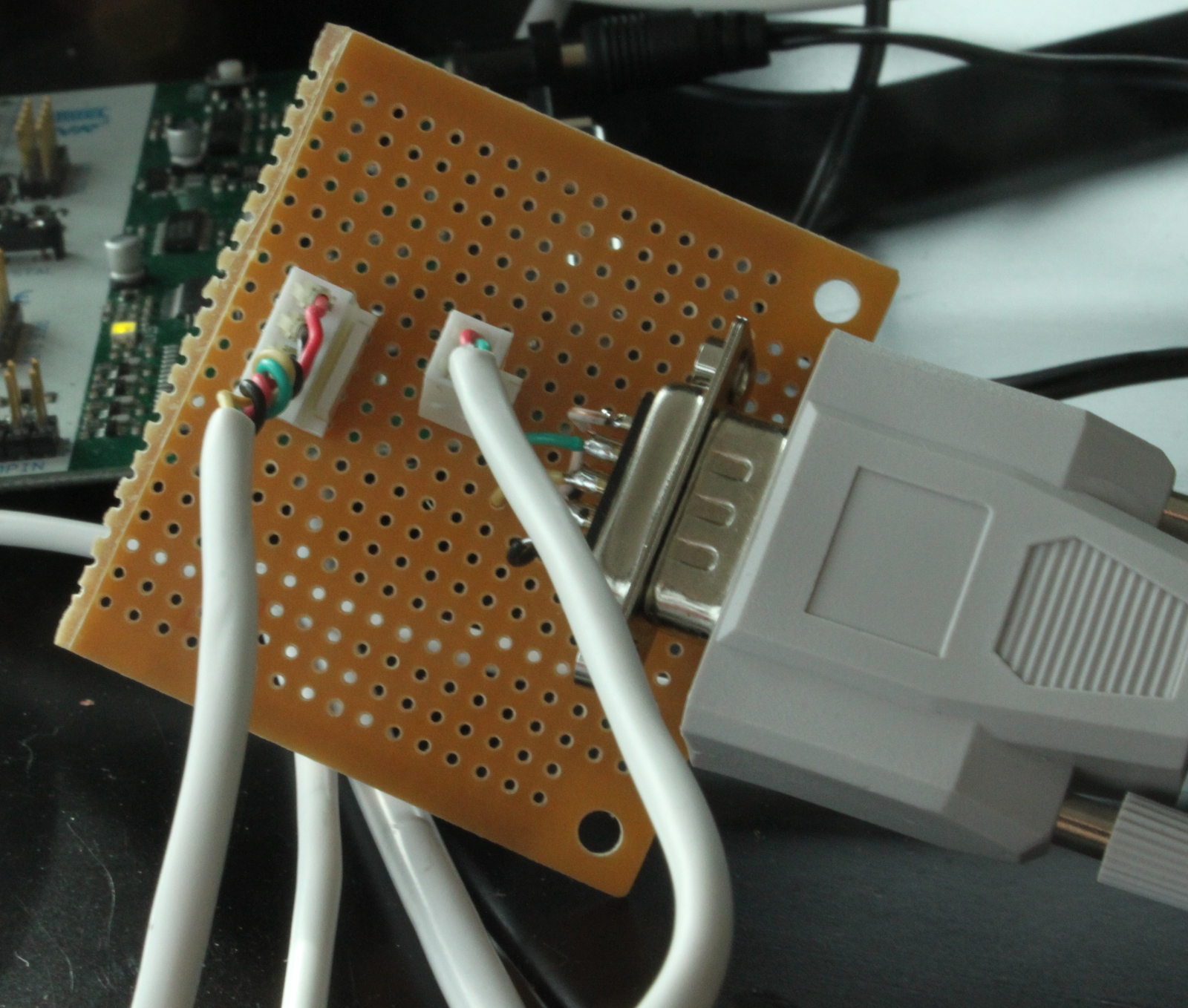
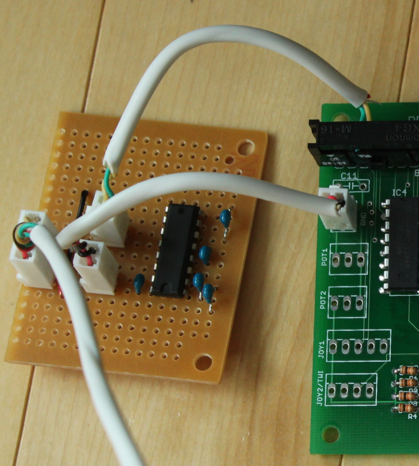
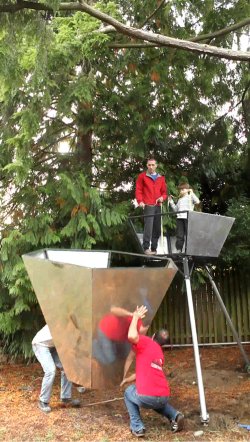
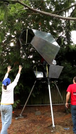

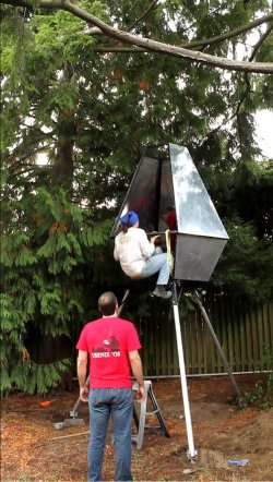
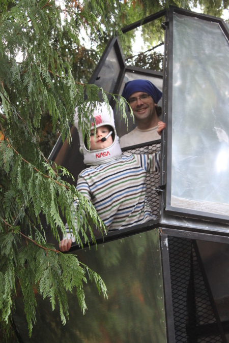 I brought out the entry hatch (at the hip level), hung it on the hinges,
and secured it with cotter pins.
Next came the window hatch (with the silicone still wet),
followed by the window screen.
I brought out the entry hatch (at the hip level), hung it on the hinges,
and secured it with cotter pins.
Next came the window hatch (with the silicone still wet),
followed by the window screen.
 The parachute straps and wide belt are pinned on in their general
planned locations. Belt carriers will be added on the shoulders and
waist to keep them in place. Hummm, looks like the shoulder strap
covers up the NASA patch, so we might have to figure out a different
place for it.
The parachute straps and wide belt are pinned on in their general
planned locations. Belt carriers will be added on the shoulders and
waist to keep them in place. Hummm, looks like the shoulder strap
covers up the NASA patch, so we might have to figure out a different
place for it.
 Just had to have the original NASA patch :v) Also I think we might
need a patch for this mission: Ravenna Ultra-Low-Altitude Vehicle
Just had to have the original NASA patch :v) Also I think we might
need a patch for this mission: Ravenna Ultra-Low-Altitude Vehicle
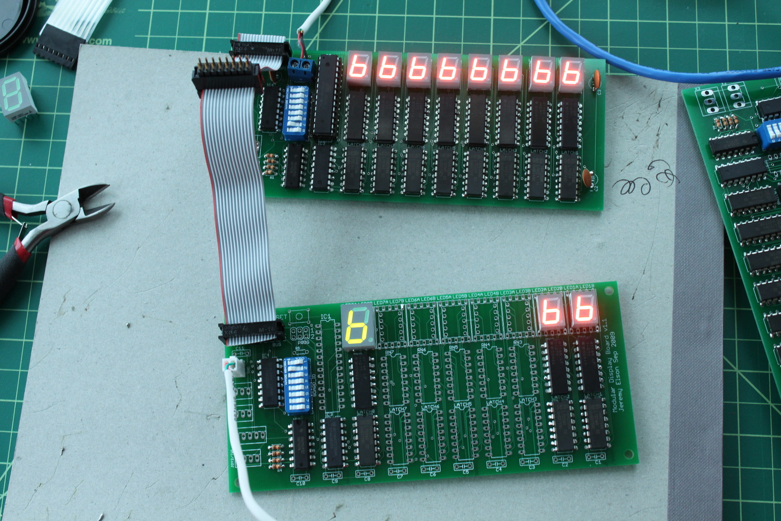

 Tonight I sat down to see if I could get the microcontroller to read
the joystick's position. I thought it would be easy; I assumed that
the top and bottom of the joystick's pot would be attached to +5V and
GND, meaning the output would be some voltage in between, linearly
mapped to the joystick's position, that could be easily read by the
ADC. But... surprise! It turns out that for some reason, joysticks
don't attach the bottom of the pot to GND, they just let it float.
They just vary their resistance, as shown in the diagram to the right.
The resistance varies between 0 and 100k ohms; 50k is center.
Tonight I sat down to see if I could get the microcontroller to read
the joystick's position. I thought it would be easy; I assumed that
the top and bottom of the joystick's pot would be attached to +5V and
GND, meaning the output would be some voltage in between, linearly
mapped to the joystick's position, that could be easily read by the
ADC. But... surprise! It turns out that for some reason, joysticks
don't attach the bottom of the pot to GND, they just let it float.
They just vary their resistance, as shown in the diagram to the right.
The resistance varies between 0 and 100k ohms; 50k is center.
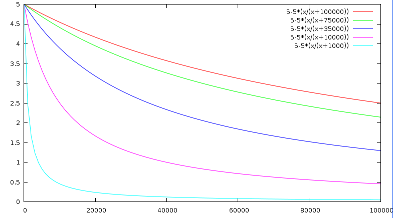


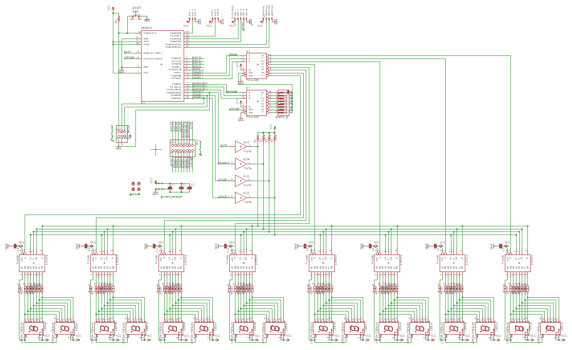
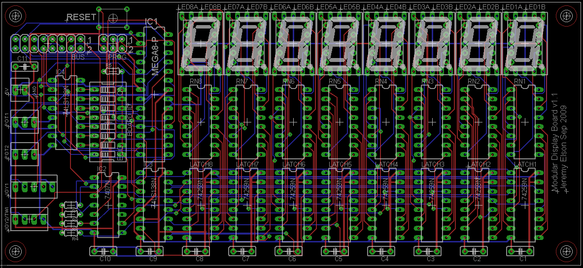
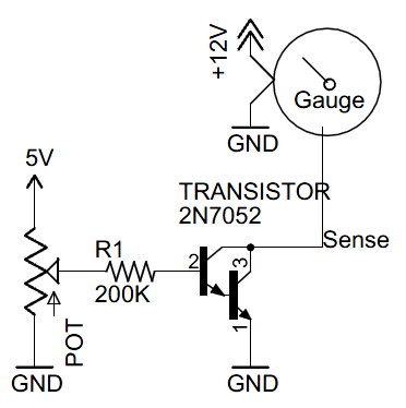 Now, on to gradually reducing this current all the way to zero,
so the gauge goes through its range of deflections.
The easiest way to do this (rather than hugely increasing the base
resistance)
is to reduce the base voltage, using a pot configured
as a voltage divider. That is, 5v and gnd on the top and bottom,
of the pot
and the base
resistor attached to the wiper, as shown in the diagram to the right.
I hooked up one of my mechanical pots and, sure enough, turning the
pot got the gauge to gradually move between its two extremes!!
Now, on to gradually reducing this current all the way to zero,
so the gauge goes through its range of deflections.
The easiest way to do this (rather than hugely increasing the base
resistance)
is to reduce the base voltage, using a pot configured
as a voltage divider. That is, 5v and gnd on the top and bottom,
of the pot
and the base
resistor attached to the wiper, as shown in the diagram to the right.
I hooked up one of my mechanical pots and, sure enough, turning the
pot got the gauge to gradually move between its two extremes!!
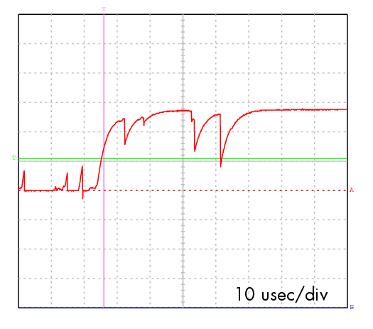 First try: breadboarded a prototype, using buttons to strobe the
inputs, and measuring the outputs with an ohmmeter. Seemed to work,
but jumped forward a lot every time I pushed the button. My little
oscilloscope confirmed that button bounce was my problem (right).
First try: breadboarded a prototype, using buttons to strobe the
inputs, and measuring the outputs with an ohmmeter. Seemed to work,
but jumped forward a lot every time I pushed the button. My little
oscilloscope confirmed that button bounce was my problem (right).
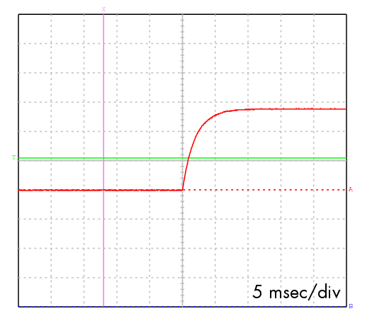 Second try:
I attached a capactior and a couple of series resistors such that
the cap would slowly charge and discharge, smoothing the signal.
It was sure nice and smooth, and was asserted far more slowly
(milliseconds rather than microseconds), but the pot still jumped
forward by several steps with each button press. Perhaps
I need a smaller cap so the voltage doesn't camp out near the
threshold for as long?
Second try:
I attached a capactior and a couple of series resistors such that
the cap would slowly charge and discharge, smoothing the signal.
It was sure nice and smooth, and was asserted far more slowly
(milliseconds rather than microseconds), but the pot still jumped
forward by several steps with each button press. Perhaps
I need a smaller cap so the voltage doesn't camp out near the
threshold for as long?
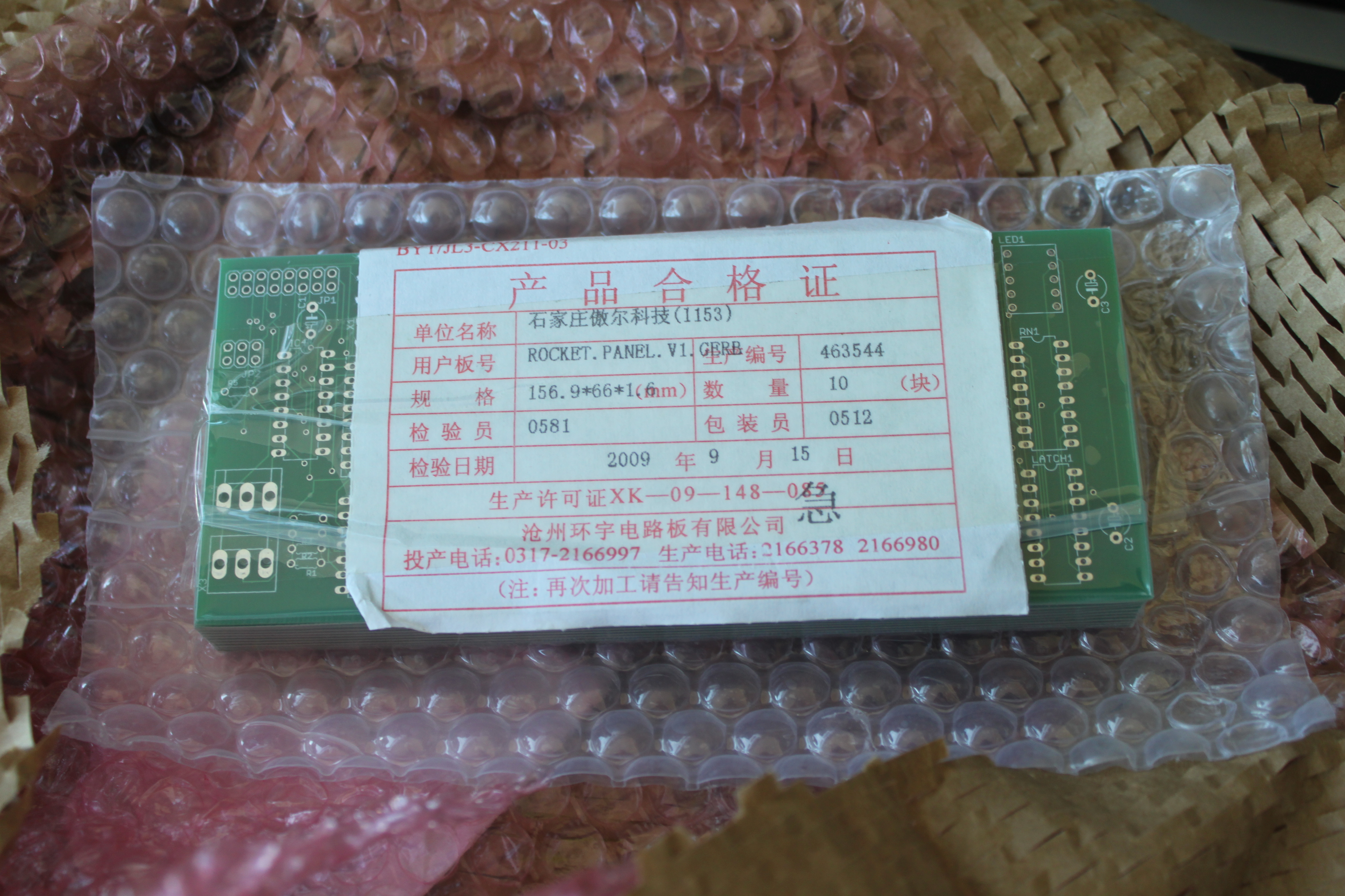
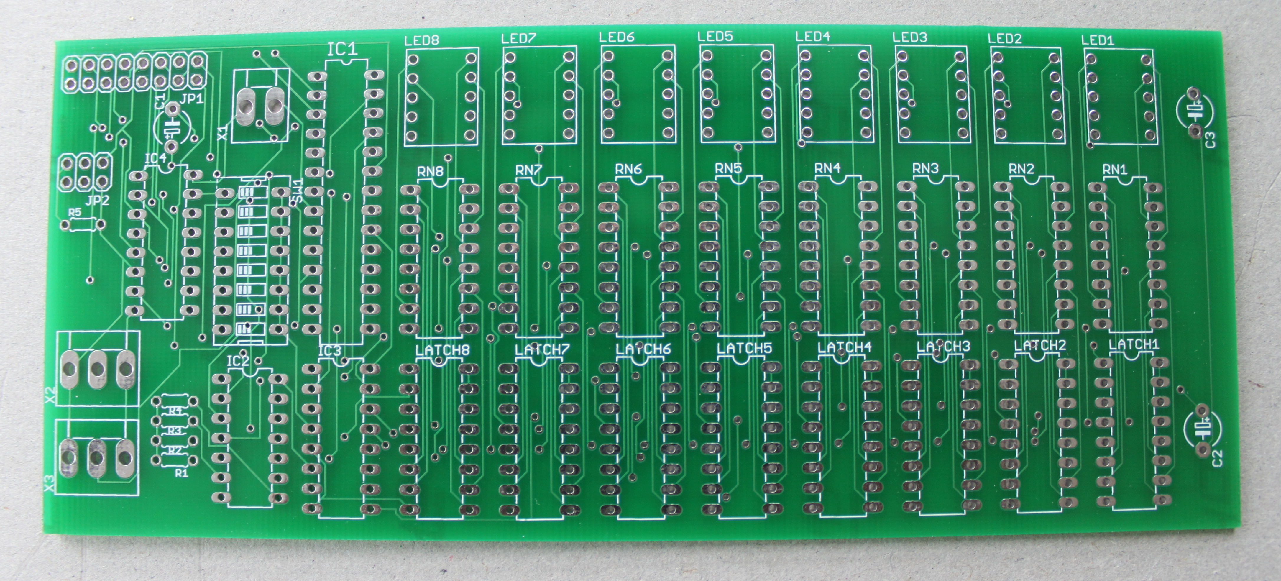
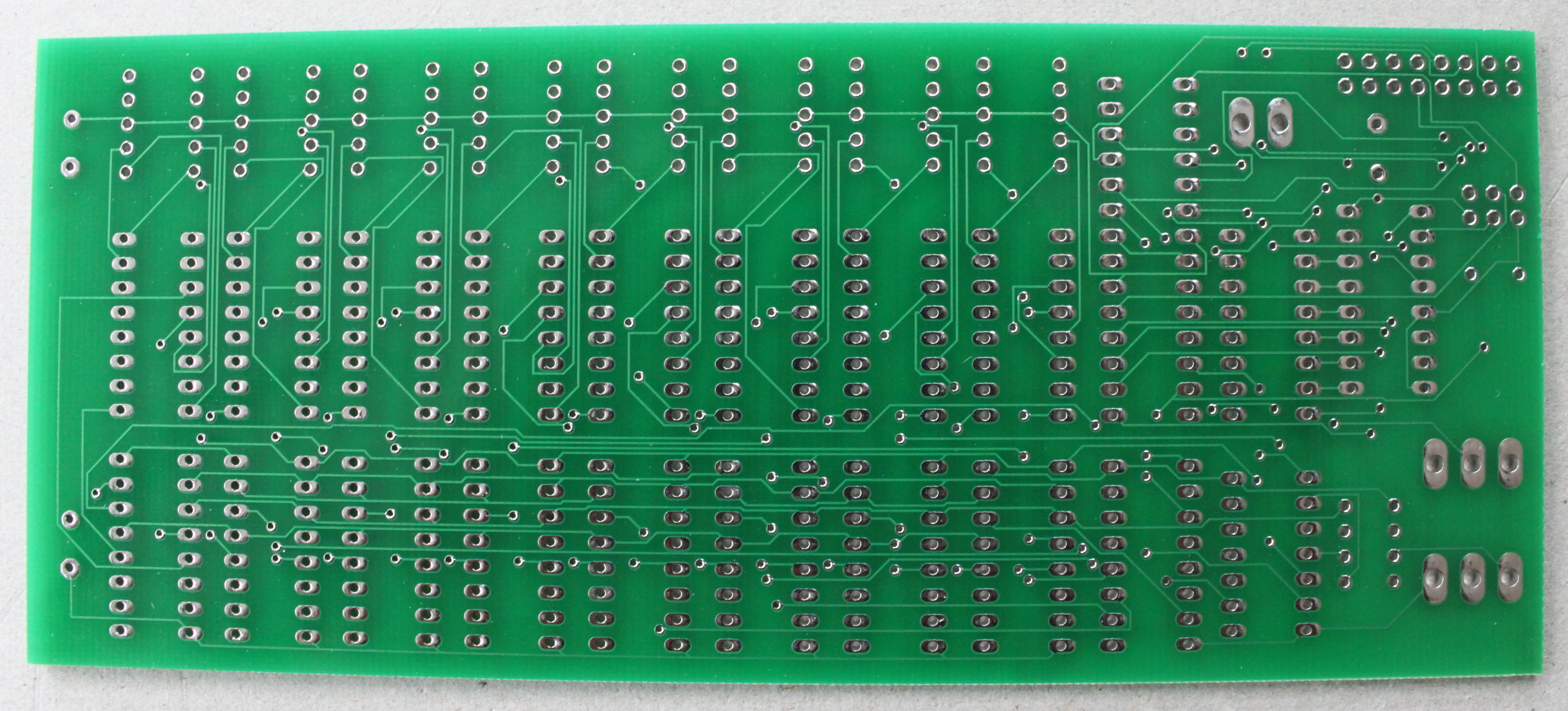
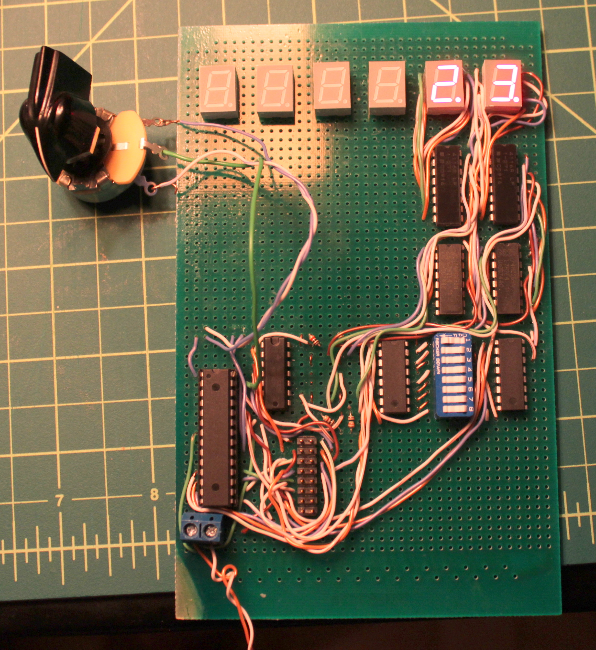
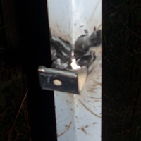 It drops into these angle brackets and bolts in place.
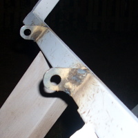 Since I had the welder out, I also welded on the eye tabs that the
rope ladder will hang from.
Since I had the welder out, I also welded on the eye tabs that the
rope ladder will hang from.
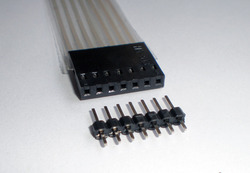
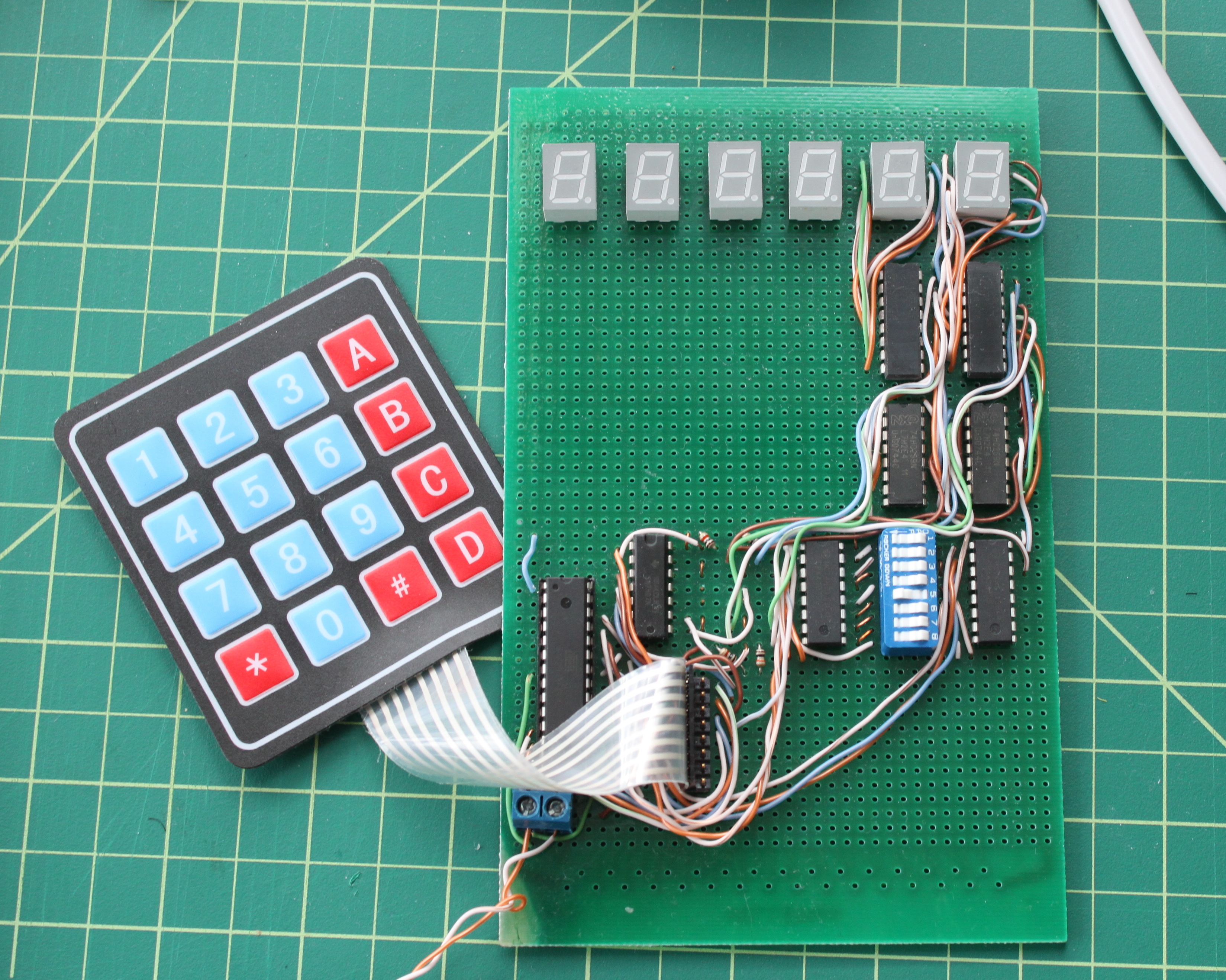
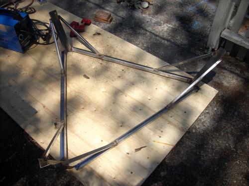 The completed frame is a rigid, gusseted triangle.
The aluminum tubes bolt into the corner sleeves of angle iron.
The opposite ends bolt to concrete pier blocks which will be buried,
adding further rigidity.
The completed frame is a rigid, gusseted triangle.
The aluminum tubes bolt into the corner sleeves of angle iron.
The opposite ends bolt to concrete pier blocks which will be buried,
adding further rigidity.
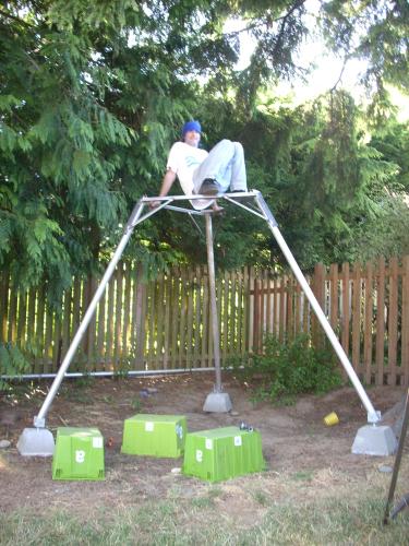 I climbed up on the assembled gantry, and it was pretty solid.
If I shake vigorously, I can get the aluminum tubes to wobble a little,
but the geometry makes it pretty difficult to put them out of column
or make them buckle.
I think this is pretty much how NASA designed the Gemini vehicles:
they'd weld something together, and then an engineer would clamber on
top, wiggle around a little, make some erudite comments, and pronounce
it flight-ready.
I climbed up on the assembled gantry, and it was pretty solid.
If I shake vigorously, I can get the aluminum tubes to wobble a little,
but the geometry makes it pretty difficult to put them out of column
or make them buckle.
I think this is pretty much how NASA designed the Gemini vehicles:
they'd weld something together, and then an engineer would clamber on
top, wiggle around a little, make some erudite comments, and pronounce
it flight-ready.
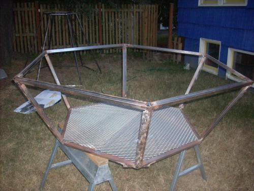 The main chassis is beginning to rust in earnest;
I'm eager to complete the welding work so I can get it painted.
Jeremy found me some cutoffs of thick expanded steel for only $40
on craigslist. The guy was in Bremerton, but no problem: Jeremy also
flew me over to Bremerton airport (KPWT) in his Cardinal.
He took the seller's kid on a trip around the pattern,
then we wrapped the steel in a tarp to avoid snagging the plane's
upholstery, and flew it back home. Ah, the $100 craigslist bargain.
I've welded a joist across the bottom hexagon,
and cut two panels of expanded steel to serve as the floor.
The main chassis is beginning to rust in earnest;
I'm eager to complete the welding work so I can get it painted.
Jeremy found me some cutoffs of thick expanded steel for only $40
on craigslist. The guy was in Bremerton, but no problem: Jeremy also
flew me over to Bremerton airport (KPWT) in his Cardinal.
He took the seller's kid on a trip around the pattern,
then we wrapped the steel in a tarp to avoid snagging the plane's
upholstery, and flew it back home. Ah, the $100 craigslist bargain.
I've welded a joist across the bottom hexagon,
and cut two panels of expanded steel to serve as the floor.
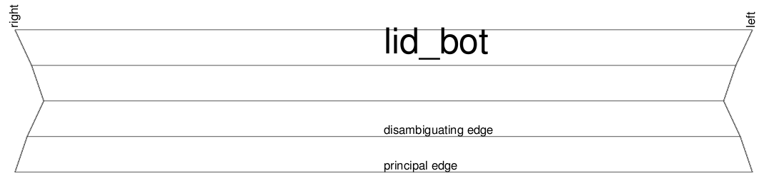
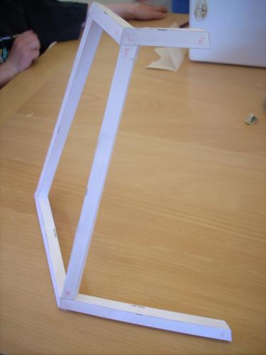
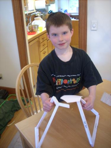
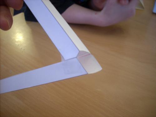 One tube on each face requires two compound cuts on one end, to
provide clearance for the bottom edge of the adjacent face.
The math was indeed hard; the paper models showed an error on pretty
much every step.
One tube on each face requires two compound cuts on one end, to
provide clearance for the bottom edge of the adjacent face.
The math was indeed hard; the paper models showed an error on pretty
much every step.
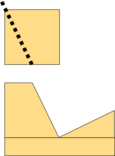
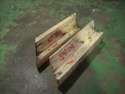 Cutting the compound angles was itself a trick, since my
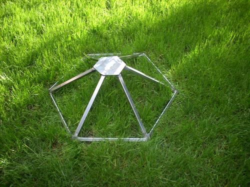
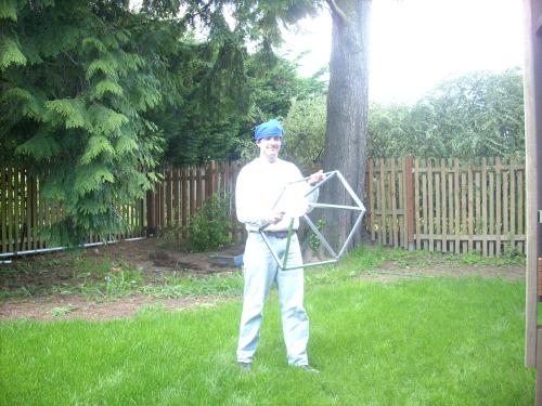
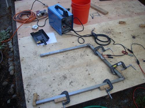
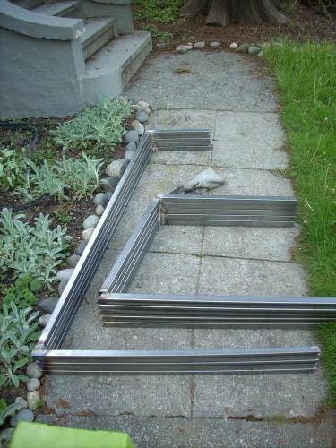
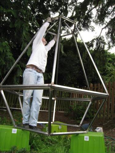
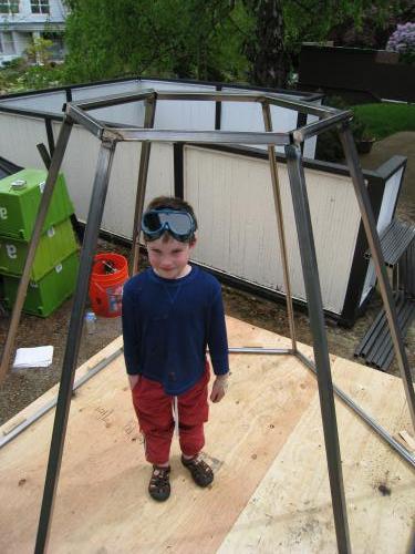 Then, to solve the challenge of holding all six pieces in place simultaneously,
I laid out the hexagonal base of the prism on the plywood platform,
screwed in pegs around the perimeter, and propped the C-shaped faces
up in the hexagon.
This worked much better than trying to freehand 30 degrees of freedom.
Imprecision made it inclined to pop out of shape,
but my friend (no, not the first-grader pictured here)
stood in the middle to hold things in place while I tacked the joints.
The final assembly came together quite nicely,
and we got to see the basic chassis together for the first time.
Then, to solve the challenge of holding all six pieces in place simultaneously,
I laid out the hexagonal base of the prism on the plywood platform,
screwed in pegs around the perimeter, and propped the C-shaped faces
up in the hexagon.
This worked much better than trying to freehand 30 degrees of freedom.
Imprecision made it inclined to pop out of shape,
but my friend (no, not the first-grader pictured here)
stood in the middle to hold things in place while I tacked the joints.
The final assembly came together quite nicely,
and we got to see the basic chassis together for the first time.
 By the way, I wondered before starting this project whether I could
get away with the
By the way, I wondered before starting this project whether I could
get away with the 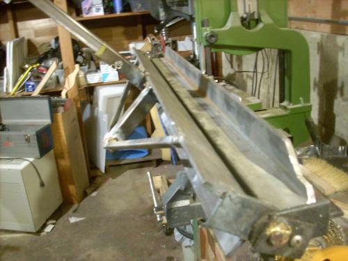 I brazed together a sheet-metal bender at my father-in-law's shop.